Adafruit Playground is a wonderful place to share what you find interesting. Have a cool project you are working on? Have a bit of code that you think others will find useful? Want to show off your electronics workbench? You have come to the right place.
Adafruit Playground is a safe place to share with the wonderful Adafruit community of makers and doers.
Click here to learn more about Adafruit Playground and how to get started.
-
DIY Bubble Machine Using Raspberry Pi Pico
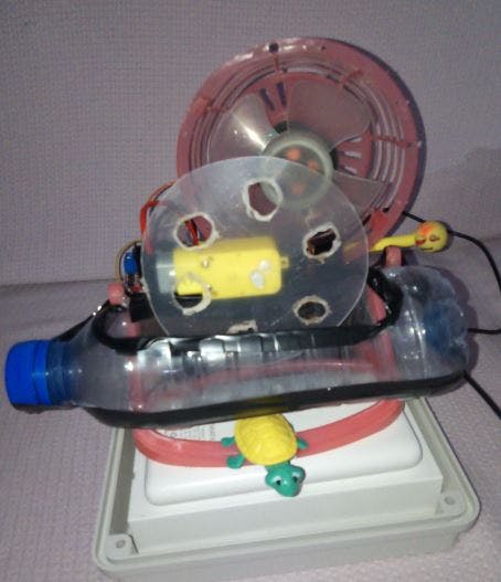
The project aims to create a soap bubble machine using a perforated plastic disc attached to a DC motor and a fan.
🫧 Introduction:
The project aims to create a soap bubble machine using a perforated plastic disc attached to a DC motor and a fan. These components are connected to an L298 driver circuit and controlled by a Raspberry Pi Pico microcontroller. This simple and enjoyable project is designed for children to learn about electronics and programming.
Soap bubbles have always fascinated children and adults alike. They bring joy and excitement, creating beautiful floating spheres that reflect light in mesmerizing colors. With this project, children can explore the science behind soap bubbles while having fun building their own machine.
The heart of the machine is the perforated plastic disc, which acts as a bubble wand. When the disc rotates, it dips into a soap solution, creating a film of soap on its surface. As the disc spins, air from the fan blows through the holes, forming bubbles that detach from the disc and float away.
To control the rotation of the disc and fan speed, we use a DC motor connected to an L298 driver circuit. The L298 driver allows us to control the direction and speed of the motor using signals from the Raspberry Pi Pico microcontroller.
We control the speed of the perforated circular bubbles disc through a potentiometer connected to an ADC pin at the Raspberry Pi Pico.
The Raspberry Pi Pico serves as the brain of our project. It runs a program that controls when to start and stop the motor, as well as adjusting its speed. By programming the Raspberry Pi Pico, children can learn about coding concepts such as loops, conditionals, and functions.
This project not only introduces children to basic electronics but also encourages their creativity by allowing them to customize their bubble machine. They can design and decorate their own plastic discs or experiment with different fan sizes for varying bubble sizes.
In conclusion, this DIY project offers an exciting opportunity for children to learn about electronics, programming, and physics while having fun creating their own soap bubble machine. It combines science with creativity in an engaging way that will captivate young minds. So let's dive into this project together and explore the fascinating world of soap bubbles!
The following picture shows the Raspberry Pi Pico pinout (which functions are supported by each pin).
🫧 How to Initialize PWM in MicroPython for Raspberry Pi Pico?
We are going to follow the steps stated below in order to configure PWM in our Raspberry Pi Pico.
- Firstly, we have to choose the PWM pin.
- Next, we set a particular frequency for our digital signal. 50Hz is a good value to start off with to work with an LED and L298.
- Raspberry Pi Pico has 12 bit resolution but in MicroPython it is scaled to 16 bits. Hence the duty cycle will be set from 0-65535 which corresponds to 0-100%
You can read this article on Raspberry Pi Pico ADC:
Inside the infinite loop we are reading the analog pin through the method read_u16() from the potentiometer variable and storing it in potentiometer_value. This value will vary from 0-65536 because we have 16 bit resolution. You will be able to see the values getting printed on the screen. This value is given as a parameter inside the duty_u16() method which is being accessed through the led and motor speed.
When you run this code on your Raspberry Pi Pico and rotate the potentiometer knob, you will get the value of ADC after every 1 seconds.
Increasing input values from the potentiometer act as increasing duty cycle hence the brightness of the led increases and the speed of motor of bubbles disk..
The blower fan and Raspberry Pi Pico were powered by a power bank. The drive module L298 is powered by an external battery.
Note:
- The smaller the disc area, the greater the possibility of bubbles sticking to each other, so it is preferable to use a larger disc with proper spacing of the holes.
- You should also use a powerful fan to blow bubbles, such as fans that rely on a Brushless motor.
- Using a variable resistor (potentiometer) we calibrate the disk speed to obtain the desired performance.
🫧 Test The Machine 🫧😊🫧
1 - Wokwi Simulation Test:
https://wokwi.com/projects/374559373412279297
2 - Real Test :
https://www.hackster.io/aula-jazmati/diy-bubble-machine-using-raspberry-pi-pico-9f2a54
-
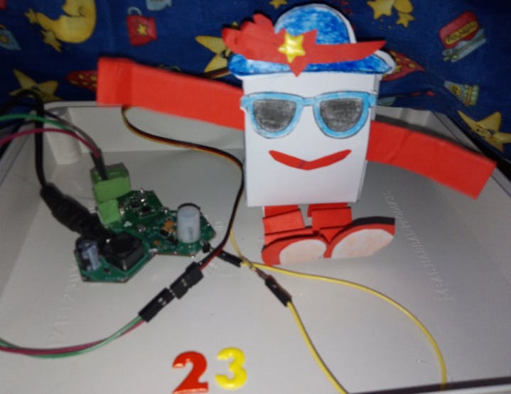
Make DIY Interactive Paper Robot
Make a robot that reacts to gestures by waving its arms in a cheer!
Introduction:
In this project, we aim to create an interactive paper robot using Hexabitz modules. The robot will be equipped with a servo motor and a motion sensor, enabling it to move its arms and wave in response to any movement detected by the sensor. By combining the versatility of Hexabitz with the simplicity of paper, we hope to create a fun and engaging DIY project that showcases the potential of modular robotics. Whether you're a beginner or an experienced maker, this project is sure to provide a rewarding challenge and a unique addition to your robotics collection. So let's get started and bring this interactive paper robot to life!
Tools:
The DIY interactive paper robot with Hexabitz is a project aimed at designing a paper robot for children using servo motors and motion sensors. The robot is capable of moving its arms and waving whenever any movement is detected in front of the sensor.
This project combines creativity, engineering, and technology to create an interactive and engaging experience for children. By using simple materials like paper and basic electronic components, we can build a fun and educational toy that encourages children to explore the world of robotics.
The main components used in this project are servo motor, which allow the robot's arms to move in different directions, and a motion sensor that detects any movement in its vicinity.
The DIY interactive paper robot not only introduces children to basic robotics concepts but also encourages them to think creatively and problem-solve. They can customize their robots by decorating them with colors, patterns, or even adding additional features like LED lights or sound effects.
Through this project, children will learn about basic electronics, coding, and how different components work together to create a functional robot. It provides an opportunity for hands-on learning and fosters curiosity and imagination.
How I build it 🛠️
Step 1: Plan the array and assemble the hardware
We prepare the project components and plan our array design by aligning modules side-by-side.
CheerBot Template: If you need to print CheerBot templates, you can download them here: https://www.okdo.com/p/okdo-microbit-build-a-paper-robot-kit
Step 2: Writing codes with STM32CubeIDE software
H0AR9x Firmware H0AR9.h code:
First, reduce the number of ports in the.h file. This can be achieved by replacing the original number of ports with one less, and commenting out the last port along with its related USART port and UART Init prototype. For example, if the original number of ports is 6, it should be reduced to 5 by commenting out (//#define _P6), (//#define _Usart6 1), and (//extern void MX_USART6_UART_Init(void);).
H0AR9x Firmware H0AR9.c code:
Second, comment the MX_USART6_UART_Init() port inside the Module_Peripheral_Init() function in the.c file, also commenting this port inside GetPort function.
H0AR9x Firmware H0AR9_gpio.c code:
Third, add the instructions for configuring the pin you are going to use in H0AR9_gpio.c file.
GPIO_InitStruct.Pin = GPIO_PIN_8;
GPIO_InitStruct.Mode = GPIO_MODE_OUTPUT_PP;
GPIO_InitStruct.Pull = GPIO_NOPULL;
GPIO_InitStruct.Speed = GPIO_SPEED_FREQ_HIGH;
HAL_GPIO_Init(GPIOB,&GPIO_InitStruct);
H0AR9x Firmware main.c code:
First, we define the motion variable:
uint16_t prox;and then defined the other variable used in the code.
int q;And in the repeated closed loop, we made sure that MCU periodically checks the
proxvalue of the sensor using the API from module factsheet.SampleDistance(&prox);And if the motion achieves the required condition (i.e. if we wave in front of the PIR motion sensor), the servo motor is turned on at certain angles to move the robot's arms.
if (q > 15)
		HAL_GPIO_WritePin(GPIOB, GPIO_PIN_8, GPIO_PIN_SET);
		Delay_ms(1.5);
		HAL_GPIO_WritePin(GPIOB, GPIO_PIN_8, GPIO_PIN_RESET);
		Delay_ms(20);
                HAL_GPIO_WritePin(GPIOB, GPIO_PIN_8, GPIO_PIN_SET);
                Delay_ms(0.5);
		HAL_GPIO_WritePin(GPIOB, GPIO_PIN_8, GPIO_PIN_RESET);
		Delay_ms(10);
                HAL_GPIO_WritePin(GPIOB, GPIO_PIN_8, GPIO_PIN_SET);
                Delay_ms(2.5);
		HAL_GPIO_WritePin(GPIOB, GPIO_PIN_8, GPIO_PIN_RESET);
Delay_ms(50);- Check out this project for : How is a Servo Controlled.
Note: For this project, make sure you're using the standard 180° servo.
Step 3: Test the System 🤖👋😊
In conclusion, the DIY interactive paper robot with Hexabitz is an exciting project that combines art, technology, and education. It offers an engaging way for children to learn about robotics while having fun building their own unique robots. Let's dive into this project and unleash our creativity!
https://www.youtube.com/watch?v=QbJlmUX6kw4
https://www.youtube.com/watch?v=TTemPlQt_nI
References: