
Adafruit Playground is a wonderful place to share what you find interesting. Have a cool project you are working on? Have a bit of code that you think others will find useful? Want to show off your electronics workbench? You have come to the right place.
Adafruit Playground is a safe place to share with the wonderful Adafruit community of makers and doers.
Click here to learn more about Adafruit Playground and how to get started.
-
Pinned by DJDevon3
About DJDevon3
I make things and I know stuff.

-
Web API's & You
- An uncomprehensive & comprehensible guide to using Adafruit Requests with web API's.
The amount of online API examples for the Adafruit_Requests library is growing. If you're interested in using an API but an example does not exist and you're unsure how to start I will help walk you through the process.
I wrote the majority of the web API examples currently in the examples directory. I'm a pretty good source on how to approach a new unknown web API and wrangle out some basic data.
JSON
Data is malleable, it can be shaped and formed in a variety of ways. The most common format currently used with REST API's is JSON. The Adafruit_Requests library is particularly good with JSON data. If you don't know how to read or write in JSON don't worry, you won't need to. The library handles all the format conversions for you. All you need to know is how to get at the data you want and I will walk you through how to do that.
Before we begin there are some glossary terms that you'll need to know in order to make sense of JSON for the web.
REST
Representational State Transfer (REST) is a software architecture that imposes conditions on how an API should work. Most web API's use the REST architecture. All a beginner needs to know about REST is it's the way a website allows you to retrieve data from an API.
Endpoint
An endpoint refers to the data to retrieve from an API. This can be part of the JSON heirarchy path or a key:value pair. For web API's typically this refers to the JSON Key:Value pair.
Key:Value
- Key:Value (always a pair separated by a colon)
A key is a unique identifier associated with data and the value is the actual data. An example would be if you're working with a weather API and might want to return current:temperature for a geographic area to display freedom units on a TFT. It would return as `current:70.0` (in Fahrenheit) or if you're living in a sensible country using the metric system it would return `current:21.1` (in Celsius).
Key Error
It's useful to know the above terms because an error that a website or Circuit Python might return is `invalid key:value pair` or simply `key error`. That error means you requested a key:value that does not exist, you spelled it incorrectly, or the request was otherwise incorrectly formatted.

-
Touchscreen TFT & SDCard with the Raspberry Pi Pico W
The goal for this project is to get the display, touch screen, and sd card working on the Pi Pico by calibrating the touchscreen and printing the contents of the sdcard to serial console.
Learning how to share multiple SPI peripherals reduces the amount of pins you need which can increase the amount of available pins for other uses. A SPI bus is very similar to an I2C bus except the SPI peripheral has a unique chip select pin assigned to it. I find it easier to think of the chip select pin as a SPI address pin. You can only have 1 address per device with I2C and the same holds true with SPI devices except the address is a physical pin.
Because SPI peripherals require a physical pin you will be limited to how many you can have based on how many free pins your microcontroller has. What SPI lacks in chain ability it makes up for with speed.
- I2C devices are half-duplex
- SPI devices are full duplex
Because SPI communication is twice as fast as I2C it makes far more sense to use SPI for displays and sd cards! Don't get me wrong, I2C definitely has its place for uses such as:
- temp sensors
- optical sensors
- 7-Segment displays
- 14-Segment displays
- small 16x9 matrix LED modules
- Neopixel strips
- and chaining a ton of devices on 1 bus without the limitation of physical pins per device.
When it comes to needing faster communication for a display that has 480x320 (153,600 total) pixels or sd card reading & writing for a single device that's where the SPI protocol outperforms I2C.
I recently worked on a project with a Raspberry Pi Pico that needed to have a Touchscreen TFT & SD Card. That's actually 3 peripherals because the touchscreen controller chip requires pins too. In the majority of scenarios when you have a SPI touchscreen you actually have 2 SPI devices, the display and the touchscreen.
In the Raspberry Pi Pico pinout diagram there are 2 separate SPI buses. SPI0 and SPI1. SPI0 peripherals cannot communicate with peripherals on the SPI1 bus and vice versa. A peripheral would be anything on the SPI protocol such as a display, sdcard, temp sensor, etc... They are highlighted below with magenta labels. Please notice that each SPI bus is prepended with SPI0 or SPI1.

-
Reading Pixels from the RA8875 Driver Board
Intro to the RA8875 Driver Board for Circuit Python
The Adafruit RA8875 driver in Circuit Python does not currently support displayio. You must use read/write registers with a barebones ra8875 graphics library. The current feature set and how it is used is only for very advanced users.
You can draw a bmp image and overlay text but you'll quickly find that's about all you can do with it. There are only 2 examples provided and the driver board is unlike any other display device for Circuit Python. Any knowledge you have of displayio does not transfer over to this board; the RA8875 is unique.
The interest of using an 800x480 bare display with Circuit Python is typically due to the sheer size of it but it should come with fair warning: You must be capable of programming with circuit python from scratch without displayio.

-
Github Desktop CRLF to LF PowerShell Workaround
The Windows Github Desktop program is an easy to use Git GUI for Windows users and it works great in most situations. However, it has a notorious history of converting every file in a Git repository checkout/clone to all CRLF (Windows Style) line endings. Line endings are also known as EOL's (End of Line).
To make line endings visible in Notepad++ go to
View > Show Symbols > Show End of LineHere's an example of what CRLF's look like when made visible.

-
12-Panel Matrix Portal Display
How many matrix panels can you use with the Matrix Portal S3? Theoretically, around 50, however the more panels you add the greater the travel distance and signal degradation. Degraded signals can have effects of pixel artifacts/glitching and visible scan lines that are very hard on the eyes.
The bit depth (amount of possible colors) is also very important. 12 panels cannot stream more than a bit depth of 4 without significant artifacts. Normally with Circuit Python, images are 8-bit indexed BMP's but matrix panels can only display a maximum of 6-bit color. A TFT can support up to 24-bit so do not make the mistake of treating a matrix display like a TFT. It will still process 8-bit indexed BMP's with some image quality loss due to the nature of RGB LED's in a matrix panel.
For this project I'm using 12x 5mm pitch matrix panels. The pitch denotes the physical distance between pixels. A 3mm pitch panel will be much smaller physically than a 6mm pitch for example.

-
Automating PIP & CircuitPython-Stubs updates for Windows Users
This article is for Circuit Python developers that use PIP and CircuitPython-Stubs in a Windows environment.
Stubs are helpers for code completion hints with IDE's such as PyCharm, VSCode, and others.
Unfortunately PIP & CircuitPython-Stubs do not automatically stay updated. These are things you must manually update when a new version of Circuit Python is released or whenever your heart dictates you want to update it. This is a problem because I never remember to keep them updated and recently found out my version of stubs was last updated in Circuit Python 7.3.3 (we're now at Circuit Python 9.0.1).

-
ESP32-S3 MQTT Feather Weather
This has been my main project since 2019 which started on the Adafruit Bluefruit Sense microcontroller with Arduino. I eventually ported it to Circuit Python... and I've never used Arduino since. There are many different versions of this project on my github that are either offline only, offline with GPS, offline & online, offline & online with MQTT.
The project I'm detailing today is offline & online with MQTT to AdafruitIO. This means if for whatever reason your WiFi goes down, OpenWeatherMap.org servers go down, or AdafruitIO goes down it will still display local sensor data and function in an offline capacity waiting patiently until communication is restored.
The display sits in front of my PC monitor and has been running 24/7 for about 3 years now. I've had a lot of time to debug all of the things that might cause it to crash, error, and gracefully fail in a never ending loop. It's not perfect but it's solidly coded.

-
Social Media Tracker (ESP32-S2)
Combines API's from: YouTube, Twitter, Github, Twitch, Mastodon, Discord
Only uses built-in adafruit_requests library, as bare bones and fast as you could want from Circuit Python. Does not use PyPortal or Portalbase libraries. You'll only need a multiplexer if your project requires more than 16 backpacks.
The only reason I'm using a multiplexer is because I intend to add more than 16, for now it's 5 rows of 2.
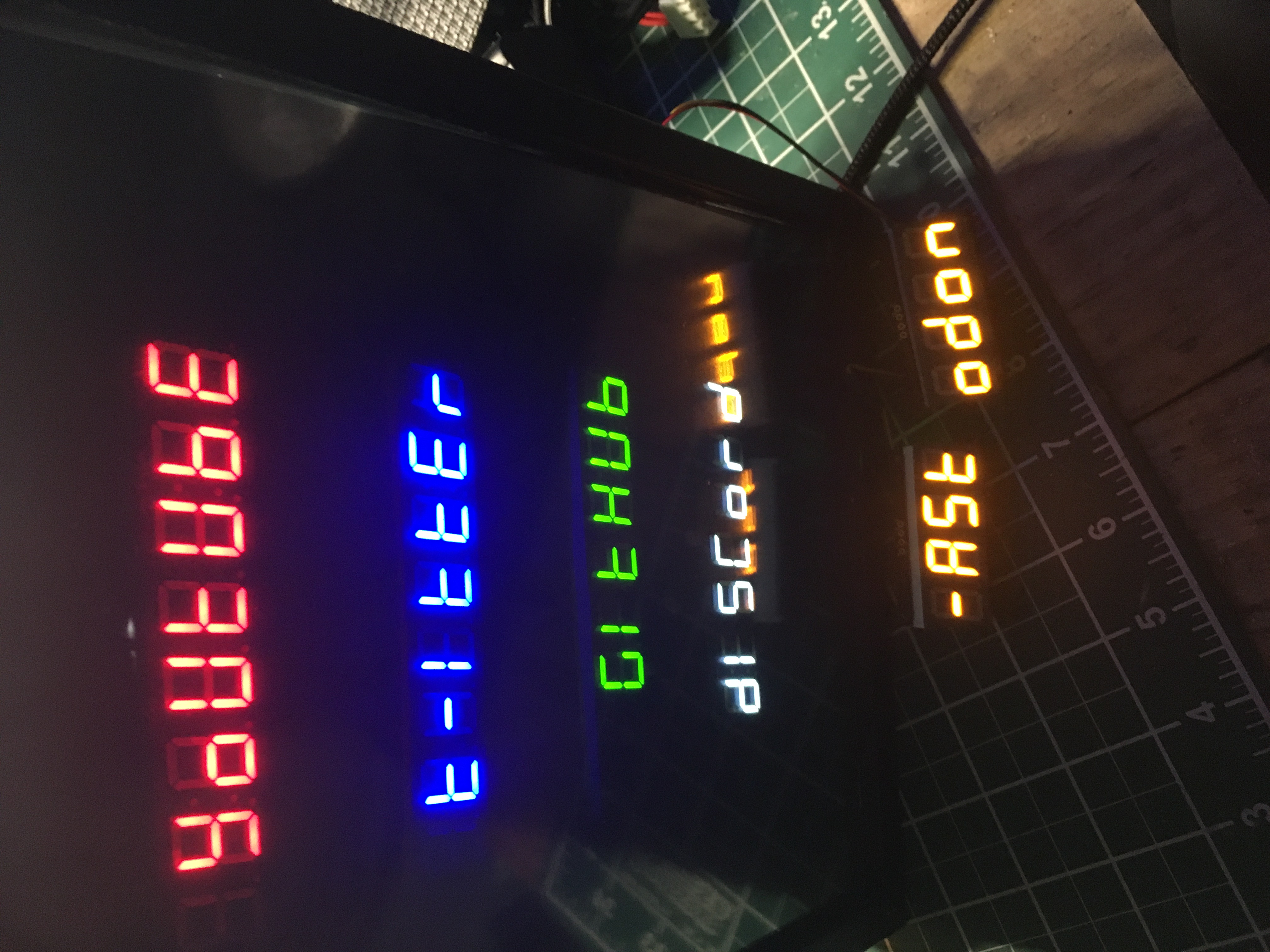 7-segment displays pulling follower counts from various social media sites