
Getting Started

Adafruit Playground is a wonderful and safe place to share your interests with Adafruit's vibrant community of makers and doers. Have a cool project you are working on? Have a bit of code that you think others will find useful? Want to show off your electronics workbench? You have come to the right place.
The goal of Adafruit Playground is to make it as simple as possible to share your work. On the Adafruit Playground users can create Notes. A note is a single-page space where you can document your topic using Adafruit's easy-to-use editor. Notes are like Guides on the Adafruit Learning System but guides are high-fidelity content curated and maintained by Adafuit. Notes are whatever you want them to be. Have fun and be kind.
Click here to learn more about Adafruit Playground and how to get started.
-
Pinned by DJDevon3
About DJDevon3
I make things and I know stuff.

-
Circuit Python Matrix Portal S3 NTP Clock
Make a highly accurate Circuit Python Matrix Panel clock quick and easy with a Matrix Portal S3 microcontroller and a 64x32 Matrix Panel.
Skill Level: Beginner
Fonts and code updates can be found in my Github Repository.

-
7" Sunton ESP32S3 8048S070 Circuit Python
Very basic primer to get your 7" Sunton ESP32S3 8048S070 display up and running on Circuit Python with displayio.
Installation
Since this board only comes with a .bin from CircuitPython.org the easiest way to install Circuit Python is to have a full Python/PIP/ESPTool environment on your PC. Then you can run esptool.py. I have a section in my personal repository on the steps to flash an ESP device on a Windows PC once you have Python and PIP installed. The other method is to use the web installer on CircuitPython.org with a Google Chrome browser.
WCH (CH340) USB Serial
Unlike most Circuit Python boards the 8048S070 does not have native usb... there is no USB drive. It's more like a classic ESP32 where you have to communicate with it via serial only. If you miss the good old days of FTDI cables and serial (no one misses those days) then you'll feel right at home.
Device Manager CH340 Driver
After installing Circuit Python and getting the board recognized in device manager it should automatically install the CH340 driver. It's a good idea to double check the serial communication speed.

-
24/7 Online Requests with CircuitPython
There might come a time when you want a project running 24/7 permanently online. Weather and Real Time Clock (RTC) updates are common uses. It's not enough to code a request to an API, you must know how to avoid every possible scenario that might crash your script. That's where error exception handlers come in.
Learning how to use exception handlers is the most important aspect of an always online script.
If you're a beginner please read Networking in Circuit Python then Web API's & You first. 24/7 Online Requests is a follow up guide for intermediate level Circuit Python coders. Some parts of this guide infer you already know the basics for getting your board online & interacting with Web API's.
The above code is as basic as it gets for attempting to connect to WiFi but what happens if your WiFi access point is down or the credentials are wrong? Your script will cease to function and will crash with an error to a console. The error could be any number of possible errors such as out of sockets, out of retries, failure to get host, and so on.
Basics of Try/Except
By wrapping the WiFi connection request in a try/except, instead of crashing to REPL, it opens some important options which include (but not limited to):
- print the error to serial console
- ignore the error completely
- retry from where try was initiated
- reload code.py
- restart the microcontroller

-
Web API's & You
Below is a test of the Playground Note code embed directly from Github (must be .md or .py file). If you see the full code below it is working as intended. If the example in the library gets updated this Playground Note might not be kept up to date with future changes. The code below will always be the most up to date as it is pulled directly from the adafruit_requests examples library.
Full Example Code
- An uncomprehensive & comprehensible guide to using Adafruit Requests with web API's.
The amount of online API examples for the Adafruit_Requests library is growing. If you're interested in using an API but an example does not exist and you're unsure how to start I will help walk you through the process.
I wrote the majority of the web API examples currently in the examples directory. I'm a pretty good source on how to approach a new unknown web API and wrangle out some basic data.
JSON
Data is malleable, it can be shaped and formed in a variety of ways. The most common format currently used with REST API's is JSON. The Adafruit_Requests library is particularly good with JSON data. If you don't know how to read or write in JSON don't worry, you won't need to. The library handles all the format conversions for you. All you need to know is how to get at the data you want and I will walk you through how to do that.
Before we begin there are some glossary terms that you'll need to know in order to make sense of JSON for the web.
REST
Representational State Transfer (REST) is a software architecture that imposes conditions on how an API should work. Most web API's use the REST architecture. All a beginner needs to know about REST is it's the way a website allows you to retrieve data from an API.
Endpoint
An endpoint refers to the data to retrieve from an API. This can be part of the JSON heirarchy path or a key:value pair. For web API's typically this refers to the JSON Key:Value pair.
Key:Value
- Key:Value (always a pair separated by a colon)
A key is a unique identifier associated with data and the value is the actual data. An example would be if you're working with a weather API and might want to return current:temperature for a geographic area to display freedom units on a TFT. It would return as `current:70.0` (in Fahrenheit) or if you're living in a sensible country using the metric system it would return `current:21.1` (in Celsius).
Key Error
It's useful to know the above terms because an error that a website or Circuit Python might return is `invalid key:value pair` or simply `key error`. That error means you requested a key:value that does not exist, you spelled it incorrectly, or the request was otherwise incorrectly formatted.

-
Touchscreen TFT & SDCard with the Raspberry Pi Pico W
The goal for this project is to get the display, touch screen, and sd card working on the Pi Pico by calibrating the touchscreen and printing the contents of the sdcard to serial console.
Learning how to share multiple SPI peripherals reduces the amount of pins you need which can increase the amount of available pins for other uses. A SPI bus is very similar to an I2C bus except the SPI peripheral has a unique chip select pin assigned to it. I find it easier to think of the chip select pin as a SPI address pin. You can only have 1 address per device with I2C and the same holds true with SPI devices except the address is a physical pin.
Because SPI peripherals require a physical pin you will be limited to how many you can have based on how many free pins your microcontroller has. What SPI lacks in chain ability it makes up for with speed.
- I2C devices are half-duplex
- SPI devices are full duplex
Because SPI communication is twice as fast as I2C it makes far more sense to use SPI for displays and sd cards! Don't get me wrong, I2C definitely has its place for uses such as:
- temp sensors
- optical sensors
- 7-Segment displays
- 14-Segment displays
- small 16x9 matrix LED modules
- Neopixel strips
- and chaining a ton of devices on 1 bus without the limitation of physical pins per device.
When it comes to needing faster communication for a display that has 480x320 (153,600 total) pixels or sd card reading & writing for a single device that's where the SPI protocol outperforms I2C.
I recently worked on a project with a Raspberry Pi Pico that needed to have a Touchscreen TFT & SD Card. That's actually 3 peripherals because the touchscreen controller chip requires pins too. In the majority of scenarios when you have a SPI touchscreen you actually have 2 SPI devices, the display and the touchscreen.
In the Raspberry Pi Pico pinout diagram there are 2 separate SPI buses. SPI0 and SPI1. SPI0 peripherals cannot communicate with peripherals on the SPI1 bus and vice versa. A peripheral would be anything on the SPI protocol such as a display, sdcard, temp sensor, etc... They are highlighted below with magenta labels. Please notice that each SPI bus is prepended with SPI0 or SPI1.
Here is the wiring setup using an Adafruit Proto Picow Doubler. The doubler offers a maximum of 3 input headers per physical pin. That means you can share up to 3 SPI devices per pin with their doubler. This is a very handy feature as I didn't have to use a breadboard to prototype this project, very cool. The reset button also came in handy during prototyping. If you have a Pi Pico I highly recommend getting one of these. They're like Feather doublers but for the Pico.

-
Reading Pixels from the RA8875 Driver Board
Intro to the RA8875 Driver Board for Circuit Python
The Adafruit RA8875 driver in Circuit Python does not currently support displayio. You must use read/write registers with a barebones ra8875 graphics library. The current feature set and how it is used is only for very advanced users.
You can draw a bmp image and overlay text but you'll quickly find that's about all you can do with it. There are only 2 examples provided and the driver board is unlike any other display device for Circuit Python. Any knowledge you have of displayio does not transfer over to this board; the RA8875 is unique.
The interest of using an 800x480 bare display with Circuit Python is typically due to the sheer size of it but it should come with fair warning: You must be capable of programming with circuit python from scratch without displayio.
The bits and bytes of binary color
Since the RA8875 can only display a maximum of 16-bit color; the 24-bit image must be converted to 16-bit (color565).
The RA8875 stores color information in its memory with 2 bytes (2 pairs of 8 bits). Here is a binary representation of how it stores the color. 11111111 00000000 There are 8 bits in 1 byte.
However the RA8875 actually stores them in what is known as swapped color565. Each first byte must be swapped with the 2nd. This is not some type of color conversion error. These are the direct reads from the memory addresses for the stored colors.

-
Github Desktop CRLF to LF PowerShell Workaround
The Windows Github Desktop program is an easy to use Git GUI for Windows users and it works great in most situations. However, it has a notorious history of converting every file in a Git repository checkout/clone to all CRLF (Windows Style) line endings. Line endings are also known as EOL's (End of Line).
To make line endings visible in Notepad++ go to
View > Show Symbols > Show End of LineHere's an example of what CRLF's look like when made visible.
All Github Desktop had to do is add a preference option to checkout and commit with LF only. No such option exists. This behavior is not present in any other Git based tool so this is a problem unique for Windows Github Desktop users. There are workarounds published online that include changing an environment variable and global git config. That workaround only works for 1 session, as soon as you close Github Desktop it will promptly ignore your previous changes. There are hundreds of issues filed about this in the Github Desktop repo over the past decade with no real solution.
There has to be a way to fix this!

-
Automating PIP & CircuitPython-Stubs updates for Windows Users
This article is for Circuit Python developers that use PIP and CircuitPython-Stubs in a Windows environment.
Stubs are helpers for code completion hints with IDE's such as PyCharm, VSCode, and others.
Unfortunately PIP & CircuitPython-Stubs do not automatically stay updated. These are things you must manually update when a new version of Circuit Python is released or whenever your heart dictates you want to update it. This is a problem because I never remember to keep them updated and recently found out my version of stubs was last updated in Circuit Python 7.3.3 (we're now at Circuit Python 9.0.1).
This is assuming you already have PIP and CircuitPython stubs installed.
The manual way to update them is:
python -m pip install --upgrade pippip install circuitpython-stubs --upgradeThese are the types of things I do not want to be required to remember to update. I consider these things minutia that should automatically stay updated.
Windows Task Scheduler can automate the process of keeping both PIP and circuitpython-stubs up to date every time you log into Windows. First we need to create a batch script and put it in a directory/folder that will always be available to Windows.
I chose to put it in the following folder:
\Downloads\CircuitPython-Stubs_UpdaterYou can name the script whatever you'd like. You can edit a .bat file as easly as a .txt file, you don't need a special IDE to do it, Notepad works fine for it.
I named my batch file:
circuitpython-stubs.batIt resides inside of the CircuitPython-Stubs_Updater folder and includes the following code in the .bat file.

-
12-Panel Matrix Portal Display
How many matrix panels can you use with the Matrix Portal S3? Theoretically, around 50, however the more panels you add the greater the travel distance and signal degradation. Degraded signals can have effects of pixel artifacts/glitching and visible scan lines that are very hard on the eyes.
The bit depth (amount of possible colors) is also very important. 12 panels cannot stream more than a bit depth of 4 without significant artifacts. Normally with Circuit Python, images are 8-bit indexed BMP's but matrix panels can only display a maximum of 6-bit color. A TFT can support up to 24-bit so do not make the mistake of treating a matrix display like a TFT. It will still process 8-bit indexed BMP's with some image quality loss due to the nature of RGB LED's in a matrix panel.
For this project I'm using 12x 5mm pitch matrix panels. The pitch denotes the physical distance between pixels. A 3mm pitch panel will be much smaller physically than a 6mm pitch for example.
Panel Arrangement
The serpentine arrangement of the panels matters. If you get it wrong you'll end up re-arranging the entire matrix until you get it right. The RGB Matrix library expects the controller (Matrix Portal S3) to be in the top right of any arrangement regardless of post-processing rotation in the code. The library expects each 2nd row to have the panels flipped 180 degrees as shown below. You can have each row or column with as many panels as you want so long as the rules of the serpentine arrangement are adhered to.

-
ESP32-S3 MQTT Feather Weather
This has been my main project since 2019 which started on the Adafruit Bluefruit Sense microcontroller with Arduino. I eventually ported it to Circuit Python... and I've never used Arduino since. There are many different versions of this project on my github that are either offline only, offline with GPS, offline & online, offline & online with MQTT.
The project I'm detailing today is offline & online with MQTT to AdafruitIO. This means if for whatever reason your WiFi goes down, OpenWeatherMap.org servers go down, or AdafruitIO goes down it will still display local sensor data and function in an offline capacity waiting patiently until communication is restored.
The display sits in front of my PC monitor and has been running 24/7 for about 3 years now. I've had a lot of time to debug all of the things that might cause it to crash, error, and gracefully fail in a never ending loop. It's not perfect but it's solidly coded.
This is the Feather Weather GUI. It incorporates API data from OpenWeatherMap.org (labels in blue) and real-time sensor data from an Adafruit BME280 module (labels in orange). It then collates the data from the BME280 sensor and whisks it away to my AdafruitIO dashboard using MQTT.
It has some additional features like showing the battery voltage and severe weather warnings. This project was designed as a battery powered weather station during hurricanes and storm related power outages.
Skill Level: Advanced: 600 lines of code
- This is not a beginner friendly project. This one is targeted at advanced Circuit Python users that have experience with JSON parsing, MQTT broker, and GUI design. There are potentially a lot of errors that might crop up during the course of this project that could get you stuck without prior experience. Help is always available in the Adafruit Discord if you want to tackle this project anyway.
- If this project seems too daunting and you'd like to try an easier version aimed more at beginners (because i was a beginner when I wrote it) then check out my Offline Feather Weather. It's only 200 lines of code.
Requirements:
- TFT display of your choosing (I'm using a 3.5" TFT Featherwing)
- OpenWeatherMap.org (free) account & API token
- AdafruitIO (free) account & API token (key)
Optional:
- Temperature/Pressure/Humidity Sensor (BME280)
- Display with built-in SDCard or SDCard module used for screenshots of your GUI.
- Adafruit LiPo battery (I'm using a 10,000 mah)

-
Social Media Tracker (ESP32-S2)
Combines API's from: YouTube, Twitter, Github, Twitch, Mastodon, Discord
Only uses built-in adafruit_requests library, as bare bones and fast as you could want from Circuit Python. Does not use PyPortal or Portalbase libraries. You'll only need a multiplexer if your project requires more than 16 backpacks.
The only reason I'm using a multiplexer is because I intend to add more than 16, for now it's 5 rows of 2.
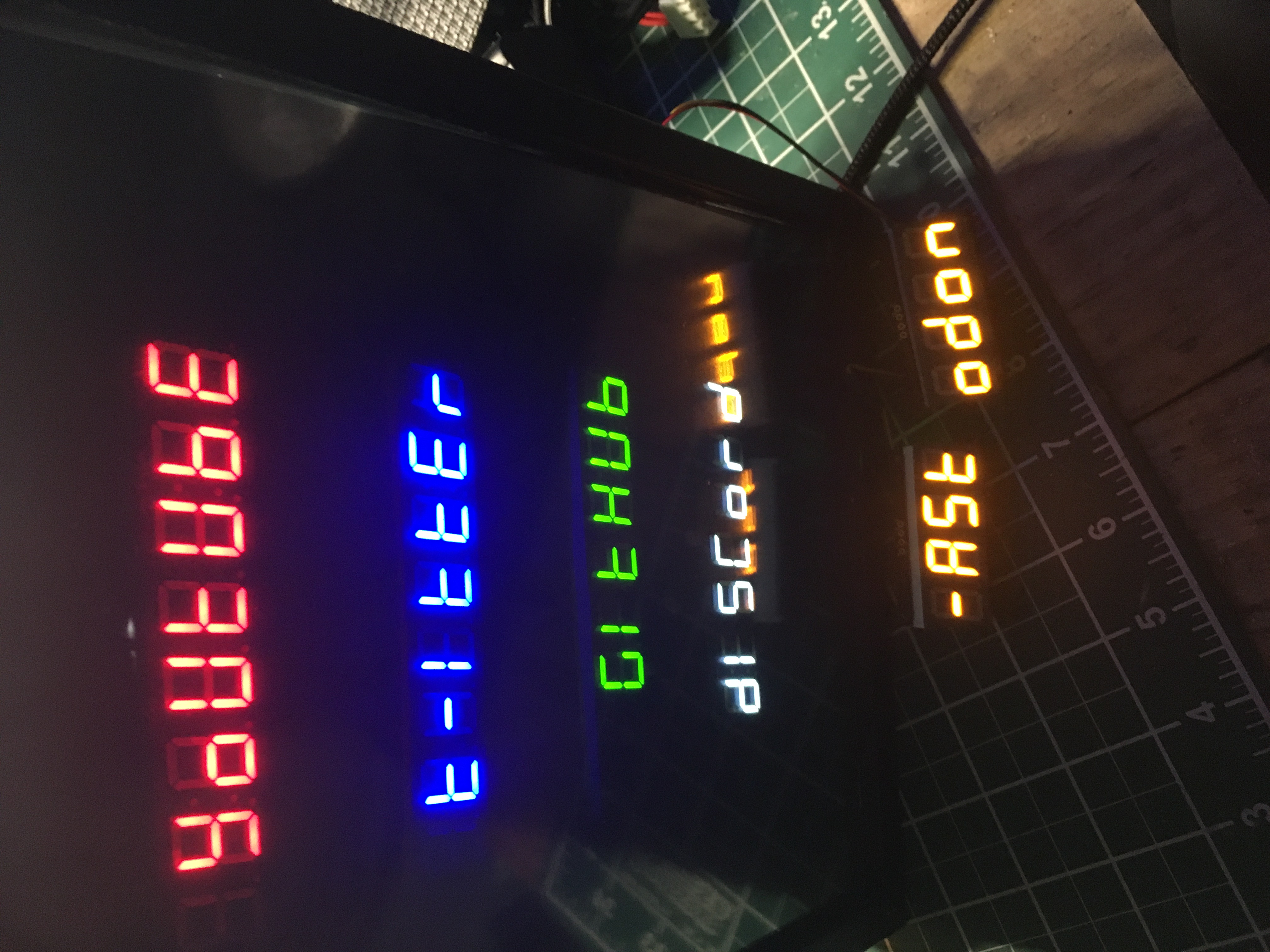 7-segment displays pulling follower counts from various social media sites