

Inspiration
Making beautiful patterns with RGB LEDs is a popular electronics project, but the possibility of generating these patterns with only a piece of flash memory, six D type flipflops, and a 555 timer was too tempting a project to pass up. I'd been puzzling over what to make from the 8 feet of dumb RGP LEDs I'd picked up from Goodwill and when someone shared this link explaining how to make a finite state machine from simple electronic components, something clicked and I couldn't stop thinking about how to combine the two "dumb" systems into something beautiful.
Materials
-
8ft of (dumb) 5V RGB LEDs
- A lucky $2 find at Goodwill
-
4, 2ft LED diffuser strips
- ~$20 (lost the original receipt, sorry)
-
Flash memory or EEPROM
- Salvaged 128KB Flash Memory (AT49F010) in my case
-
5, D type flipflops
- Salvaged SN74LS174N IC
-
555 Timer IC (or other clock source)
- Salvaged IC from an ancient computer motherboard
-
Perfboard
- New, 8 segments of an ElectroCookie PCB Prototype Board
-
NPN BJT x11 (8 bit indicators + 3 LED strip drivers)
- Salvaged from an ancient (and broken) oscilloscope
-
Potentiometer
- New, in a kit with other things
-
Micro Switches
- Salvaged
-
8x Red Indicator LED (for displaying the current byte of memory)
- Part of a bag from a garage sale, estimated cost <$0.10
-
5V Power Supply
- A broken USB cable found in the road
-
3D Printed Case (TBD)
- TBD
-
Misc caps, resistors, indicator LED, wires, and chip sockets
- Salvaged or spare
The salvage percentage is especially hard to calculate on this one since several items are purchased, but not new. My guesstimate will be based on the market value of a similar system vs the cost of the parts I acquired to create my own. I'm going to ballpark a similar set of RGB LEDs with a few predetermined patterns at about $100, the total cost for my parts was only around $22, so I'm going to call this one 78% salvaged.
Initial Testing
So, my piece of memory has 17 address pins (217 is 131,072 possible addresses) and 8 data pins. There is one byte (8 bits) of data stored at every combination of those 17 address pins. In the picture above I'm using a tiny set of switches (right) to change some of the address values on the memory chip (middle) and routing the data pins to toggle on and off 8 LEDs (left) as a way of displaying the data stored at each address. Most memory chips aren't designed to source or sink any significant amount of current, so the black blobs just below each LED are transistors that allow the LEDs to be powered directly from the 5V line but controlled by the digital signal from the flash memory.
Design
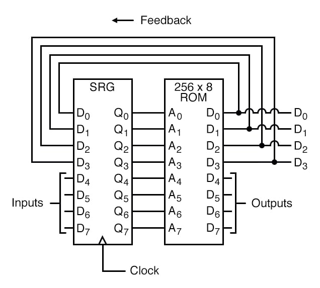
Now, imagine that instead of controlling 8 red LEDs, I split the output so that the top 5 bits were used to toggle those switches and each of the bottom three were used control a (very large) red, green, and blue LED independently. Every address in memory can now be thought of as containing a display pattern in RGB and part of the next address in the sequence.
One downside of only having 8 data bits to work with is that...
Now, how to automatically toggle those switches?