Getting Started

Adafruit Playground is a wonderful and safe place to share your interests with Adafruit's vibrant community of makers and doers. Have a cool project you are working on? Have a bit of code that you think others will find useful? Want to show off your electronics workbench? You have come to the right place.
The goal of Adafruit Playground is to make it as simple as possible to share your work. On the Adafruit Playground users can create Notes. A note is a single-page space where you can document your topic using Adafruit's easy-to-use editor. Notes are like Guides on the Adafruit Learning System but guides are high-fidelity content curated and maintained by Adafuit. Notes are whatever you want them to be. Have fun and be kind.
Click here to learn more about Adafruit Playground and how to get started.
-
Pyboom - A game for the Fruit Jam Py-Boom
Py-Boom is a fast-paced, 8-bit-style arcade game written in CircuitPython for the Adafruit Fruit Jam and other compatible display boards.
This game is a modern take on a classic "catcher" formula, featuring both a single-player mode against an AI and a competitive two-player versus mode.
Game Modes
At the title screen, you can select your game mode:
-
1-Player Mode: You control the Bucket (P1) at the bottom of the screen. An AI-controlled Bomber moves at the top, dropping bombs at an increasing rate. Your goal is to catch as many bombs as possible to survive the level.
-
2-Player Mode: Player 1 controls the Bucket, and Player 2 controls the Bomber. P1's goal is to survive, while P2's goal is to drop bombs strategically to make P1 miss.
How to Play
P1 (Bucket) - The Catcher
-
Goal: Catch every bomb that is dropped. If you miss a bomb, you lose one of your buckets (lives). If you lose all three, the game is over.
-
Winning: If you (P1) successfully catch all bombs in a level (e.g., 10 bombs in Level 1), you win the round and advance to the next, more difficult level.
P2 (Bomber) - The Attacker
-
Goal: Make P1 miss! You have a limited number of bombs per level. Use your movement and timing to drop bombs where P1 isn't.
-
Winning: If you (P2) successfully make P1 lose all three of their buckets, you win the game!
Controls
Action
Player 1 (Bucket)
Player 2 (Bomber)
Move Left
AkeyLeft ArrowkeyMove Right
DkeyRight ArrowkeyDrop Bomb
N/A
Down ArrowkeyStart / Ready
SpacebarEnterkeyOther Controls
-
Select Mode: On the title screen, press the
1or2key. -
Restart Game: On the "Game Over" screen, press the
Rkey to return to the title screen.
Required Files
To run this game, you will need the following files on your CircuitPython device:
-
code.py: The main game code. -
The Fruit Jam OS library package.
-
pyboom.bmp: The title screen logo. -
bomb_icon.bmp: The bomb sprite icon (used in development).
Download at: Pyboom Git Hub
Background
This project was started on Microsoft Make Code for my Pygamer and was called Prison Break. With the introduction of the Fruit Jam I wanted to port this over to Circuit Python. The graphics in Make Code (MC) are saved in a TypeScript file so I had to copy the codes for the sprites over to my Circuit Python. I used the AI tools that are part of Visual Studio Code (VS) the develop functions to map the sprites maps into bitmaps and tile grids. I continued to use the AI tools to help convert the Python code from MC. I mostly used Gemini as I have 3 months of premium from purchasing my phone. Though there were times where Gemini would get stuck on fixing issues it was making so I would switch to the free tokens in VS and use Claude or Chat-GPT. I ran out of free tokens in VS and moved on to Gemini for versions 2 and 3 of the game. I am in the process of uploading my prompts that I still have access to (I lost my VS conversations :( ) and hope to have them done in the next week. I also hope to get controllers setup and maybe make paddle controllers in the future.
I found this a fun project to learn Circuit Python and coding with AI. I'm still learning the concepts of using classes and learned a lot while looking at the errors the AI was coming up with.
-
-
Fizzgig I built Fizzgig and would like to share a few notes on my build (made in October 2025). I hope that this is helpful to anyone attempting to build it as well. I had a lot of fun building it!
Speaker
I tried using an external speaker connected with the headphone jack cable. It turned out that this speaker is not deactivated when no sound is played, and it produces very loud white noise (this happens with any speaker connected via this connection). Thankfully, the Adafruit support team reproduced this, and it seems that this behaviour cannot be resolved. So I went along with the oval mini speaker that is connected to the board via PicoBlade. To improve its sound a little, I attached the speaker to a Tic Tac box as a resonator, which worked quite well.
Servo / Jaw
I used lots of hot glue to attach all the hair, so the jaw became rather heavy. I attached some cardboard to the jaw to stabilise it, but this was not enough to support the weight. As a result, the jaw would not close properly. To resolve this, I stabilised the jaw with ice cream sticks. I also extended the servo horn with a piece of carbon tube. I could securely fix this to the servo horn using heat shrink tube with hot glue. My extended servo horn ends in a grommet made out of another piece of carbon tube with a larger diameter that I glued to the jaw. This makes the placement of the servo a lot easier and the connection more stable.
I thought about also adding a spring taken out of a retractable pen to the servo horn extension to help the servo along. In my build, this was not possible to integrate, but there may be setups where adding a spring is possible and makes sense.
Since I could not use a spring, I added a counterweight in the part where the servo horn ends. I glued in a screw and added two nuts for added weight. This helps the servo along.
Code
I used the UF2 file provided in the instruction. I would have liked to change the code to reduce the jaw opening angle (this would have enabled me to use a spring). Adafruit support pointed me to the code, and I was able to identify the place where the servo angles are defined. In my current Arduino IDE, the code would compile successfully, and the IDE even told me that the code had been successfully transferred to the board. However, CIRCUITPY was still visible as a drive after this supposedly successful transfer, and I had to re-upload the original UF2 file to go back to that version. I re-tried with several different methods, but I was not able to make the compiled code transfer to the board successfully. This may be due to my inability, since I am not very experienced using microcontrollers at all. If you are planning to alter the code, do check if it works for you before making your build.
Wig
It makes a lot of sense to buy a wig with really long hair. The instructions advise to cut off the hair along the longest section. I did this, but it would have made more sense to plan ahead to first check where the nose will go. Most hair under the nose will not be needed, as that's where the mouth goes. Depending what your particular wig looks like, it may be better to keep the long hair in the back and trim under the nose.
Also, the hair will be all over the place when you're done.
I styled my Fizzgig's hair with transparent lacquer from a spray can. This was necessary especially around the eyes and the nose.
Frame
I built a wooden frame for my Fizzgig. I had originally used a cardboard box, but for more stability I replaced it with a wooden frame that basically had the same dimensions. My frame is about 31 x 18 x 10 cm. The required dimensions very much depend on the size of the wig and the length of the hair.

-
Magnetometer - MMC5603 to measure gas usage inside your home with home assistant I wanted to measure the gas usage inside my home and push the data into Home Assistant.
To collect the data, I wanted to use the MMC5603 magnetometer + ESP32 Feather V2. The MMC5603 had a great price point and the ESP32 Feather V2 was able to connect to my Home Assistant server via WiFi.
Requirements
- ESPHome 2025.8.3
- The Adafruit Products above (MMC5603 + ESP32 Feather V2 or similar board that can connect via WiFi)
- Ethernet Cable (Cat 5 and later is fine)
- USB Power Adapter (e.g. like this one , 5V 1A)
- A short USB-A to USB-C connector (e.g. like this one, data isn't important here - so any cable will do)
- M2.5 screws (lengths and materials will be up to you, I used nylon M2.5 screws to attach the bracket to the gas meter and metal M2.5 screws for the MMC5603 to the bracket).
If you end up using any earlier version of ESPHome and you'll run into issues like I did where the MMC5603 wasn't being registered properly.
I connected everything like this diagram:
I ended up having to create a 3D bracket that could hold the MMC5603 onto the US Gas Meter.
https://www.printables.com/model/1446364-us-gas-meter-brace-for-a-mmc5603-magnetometer
-
Your own TTS engine for the Fruit Jam Spell Jam app Overview
The Spell Jam app on the Fruit Jam is a twist on a classic electronic toy. Check out the Spell Jam learn guide to learn all about it.
By default, Spell Jam uses the Amazon Polly Text-to-Speech (TTS) service to create audio from the entered text. While Amazon's service can be used for free during a trial period, it does require an AWS account.
If you'd prefer not to create an Amazon AWS account, you can instead run a local TTS server on your home network using open-source models like KittenTTS, Kani-TTS or eSpeak.
This playground will walk you through the steps required to run a local TTS server on your network and configure Spell Jam on your Fruit Jam to use that server instead of AWS.
Installing a Text-to-Speech Model
There are two TTS AI models that the Spell Jam local backend works with:
- KittenTTS - lightweight, will run on a Raspberry Pi 4/5
- Kani-TTS - newer, but may require an Nvidia GPU. (as of 2/2026 Kani no longer works with server.py)
Legacy software TTS application:
- eSpeak - Initially released in 2006, a free and open-source compact speech synthesizer.
Before install any of the TTS systems, create and/or activate a dedicated Python virtual environment.
python3 -m venv venv
source venv/bin/activate
-
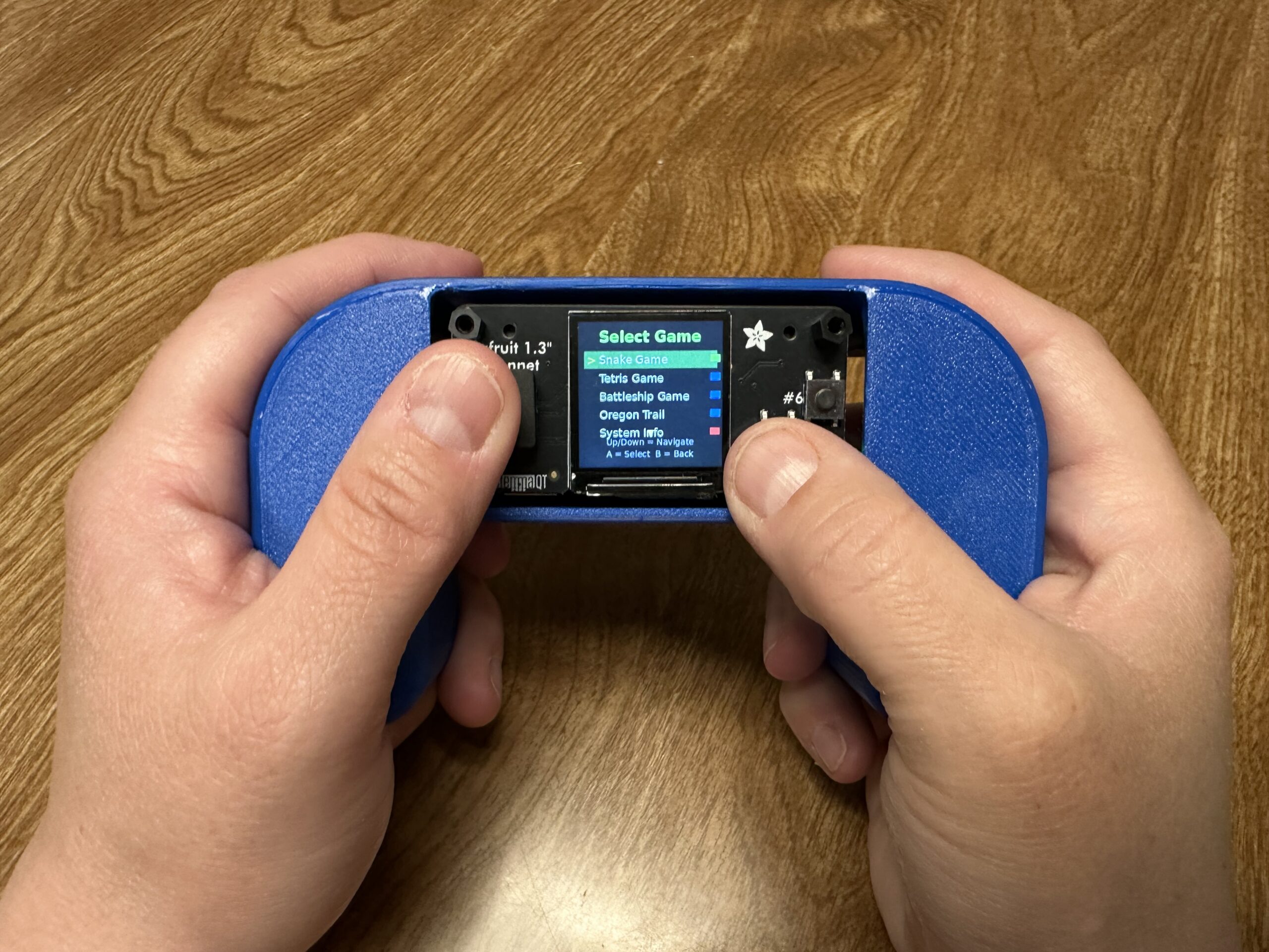
Herman Entertainment System (Pi Zero2w Python Handheld) This is the Herman Entertainment System, a handheld gaming system with a Raspberry Pi Zero 2 W and the Adafruit 1.3″ TFT Bonnet. Why Herman? I don’t know, that is what the kids wanted to call it, apparently Herman needs entertained. As for why we needed this instead of an existing emulator, well this particular setup struggles to run systems like RetroPie due to a display issue, so we created a small setup that uses Python and creates a home screen that lists all the games on the device and you simply choose which to play. It automatically updates with all the games you have added, in our example we have a Snake game, but you can add or make nearly anything. Print files for the enclosure are available here via Printables, and additional details and instructions are available here.
Step 1: Prepare the SD Card (Headless Setup)
Flash Pi OS Lite
- Download Raspberry Pi Imager from raspberrypi.org
- Insert your SD card into your computer
- Open Raspberry Pi Imager
- Choose “Raspberry Pi OS Lite (32-bit)” – no desktop needed
- Click the gear icon (Advanced options) and configure:
- Enable SSH ✓
-
Set username:
herman - Set password: (your choice)
- Configure WiFi: Enter your network name and password
- Set locale settings: Your country/timezone
- Flash the image to SD card
Step 2: First Boot and SSH Connection
- Insert SD card into your Pi Zero 2 W
- Power on the Pi (green LED should flash, then stay solid)
- Wait 2-3 minutes for first boot to complete
-
Find the Pi’s IP address:
- Check your router’s admin page for connected devices
- Or use an IP scanner like Advanced IP Scanner
- Look for device named “raspberrypi”
Connect via SSH
ssh [email protected]
# Replace XXX with your Pi's actual IP address
Enter your password when prompted.
Step 3: System Updates and Basic Setup
# Update the system
sudo apt update && sudo apt upgrade -y

# Install essential packages
sudo apt install python3-pip python3-pil git -y

# Enable SPI (required for TFT display)
sudo raspi-config
In raspi-config:
- Go to Interface Options → SPI → Enable
- Finish and reboot
Reconnect via SSH after reboot.
Step 4: Install TFT Display Libraries
Note: Newer Pi OS versions require
--break-system-packagesflag# Install compatible Adafruit libraries sudo pip3 install "adafruit-circuitpython-rgb-display==3.10.0" --break-system-packages sudo pip3 install "adafruit-circuitpython-busdevice==5.2.0" --break-system-packages sudo pip3 install "adafruit-circuitpython-typing==1.10.1" --break-system-packages # Install additional required libraries for SPI configuration sudo pip3 install click --break-system-packages sudo pip3 install adafruit-python-shell --break-system-packages # Install system packages sudo apt install python3-numpy -y
Step 5: Configure TFT Display Hardware
# Download and run the SPI configuration script
wget https://raw.githubusercontent.com/adafruit/Raspberry-Pi-Installer-Scripts/main/raspi-spi-reassign.py
sudo python3 raspi-spi-reassign.py
When prompted:
- Select 1 Reassign SPI Chip Enable Pins
- For CE0 selection, choose 22 Disabled
- Reboot when prompted
Step 6: Create the Gaming System Files
Reconnect via SSH and create your gaming system:
# Create directories
mkdir -p /home/herman/games
mkdir -p /home/herman/system
Create the main entertainment system:
nano /home/herman/herman_entertainment_system.py

Then copy the following code and paste it into the new file.


#!/usr/bin/env python3
import time
import os
import subprocess
import digitalio
import board
import importlib.util
import sys
from adafruit_rgb_display.rgb import color565
from adafruit_rgb_display import st7789
import RPi.GPIO as GPIO
from PIL import Image, ImageDraw, ImageFont

class HermanEntertainmentSystem:
    def __init__(self):
        # Initialize display and GPIO in the class
        self.setup_hardware()

        # Load fonts
        try:
            self.font_huge = ImageFont.truetype("/usr/share/fonts/truetype/dejavu/DejaVuSans-Bold.ttf", 36)
            self.font_large = ImageFont.truetype("/usr/share/fonts/truetype/dejavu/DejaVuSans-Bold.ttf", 24)
            self.font_medium = ImageFont.truetype("/usr/share/fonts/truetype/dejavu/DejaVuSans.ttf", 18)
            self.font_small = ImageFont.truetype("/usr/share/fonts/truetype/dejavu/DejaVuSans.ttf", 14)
        except:
            self.font_huge = ImageFont.load_default()
            self.font_large = ImageFont.load_default()
            self.font_medium = ImageFont.load_default()
            self.font_small = ImageFont.load_default()

        # Button debouncing
        self.last_button_time = 0
        self.button_debounce = 0.2

        # Game list
        self.games = []
        self.selected_game = 0
        self.games_directory = "/home/herman/games"

        # Create games directory if it doesn't exist
        if not os.path.exists(self.games_directory):
            os.makedirs(self.games_directory)

        self.scan_for_games()

    def setup_hardware(self):
        """Initialize display and GPIO"""
        # TFT Display Setup
        self.cs_pin = digitalio.DigitalInOut(board.CE0)
        self.dc_pin = digitalio.DigitalInOut(board.D25)
        reset_pin = None
        BAUDRATE = 40000000

        self.display = st7789.ST7789(
            board.SPI(),
            cs=self.cs_pin,
            dc=self.dc_pin,
            rst=reset_pin,
            baudrate=BAUDRATE,
            width=240,
            height=240,
            x_offset=0,
            y_offset=80,
            rotation=180,  # Fixed rotation for proper orientation
        )

        self.backlight = digitalio.DigitalInOut(board.D26)
        self.backlight.switch_to_output()
        self.backlight.value = True

        # GPIO Setup - Correct pins for Pi Zero 2 W + TFT Bonnet
        GPIO.setmode(GPIO.BCM)
        GPIO.setup(17, GPIO.IN, pull_up_down=GPIO.PUD_UP)  # UP
        GPIO.setup(22, GPIO.IN, pull_up_down=GPIO.PUD_UP)  # DOWN
        GPIO.setup(27, GPIO.IN, pull_up_down=GPIO.PUD_UP)  # LEFT
        GPIO.setup(23, GPIO.IN, pull_up_down=GPIO.PUD_UP)  # RIGHT
        GPIO.setup(5, GPIO.IN, pull_up_down=GPIO.PUD_UP)   # Button A
        GPIO.setup(6, GPIO.IN, pull_up_down=GPIO.PUD_UP)   # Button B
        GPIO.setup(4, GPIO.IN, pull_up_down=GPIO.PUD_UP)   # Button C


    def get_text_size(self, draw, text, font):
        """Compatible text size function for older PIL versions"""
        try:
            bbox = draw.textbbox((0, 0), text, font=font)
            return bbox[2] - bbox[0], bbox[3] - bbox[1]
        except AttributeError:
            try:
                return draw.textsize(text, font=font)
            except:
                return len(text) * 8, 16

    def draw_centered_text(self, draw, text, y_pos, font, color):
        """Draw text centered horizontally"""
        text_width, text_height = self.get_text_size(draw, text, font)
        x_pos = (240 - text_width) // 2
        draw.text((x_pos, y_pos), text, font=font, fill=color)
        return text_height

    def read_controls_debounced(self):
        """Read controls with debouncing"""
        current_time = time.time()

        raw_controls = {
            'up': not GPIO.input(17),
            'down': not GPIO.input(22),
            'left': not GPIO.input(27),
            'right': not GPIO.input(23),
            'button_a': not GPIO.input(5),
            'button_b': not GPIO.input(6),
            'button_c': not GPIO.input(4)
        }

        # Apply debouncing
        if current_time - self.last_button_time > self.button_debounce:
            if any(raw_controls.values()):
                self.last_button_time = current_time
                return raw_controls

        return {key: False for key in raw_controls}

    def scan_for_games(self):
        """Scan for available game files"""
        self.games = []

        # Add built-in games
        builtin_games = [
            {"name": "Snake Game", "file": "snake_game_module.py", "type": "builtin"},
        ]

        for game in builtin_games:
            if os.path.exists(f"/home/herman/{game['file']}"):
                self.games.append(game)

        # Scan games directory for additional games
        if os.path.exists(self.games_directory):
            for filename in os.listdir(self.games_directory):
                if filename.endswith('.py'):
                    game_name = filename.replace('.py', '').replace('_', ' ').title()
                    self.games.append({
                        "name": game_name,
                        "file": filename,
                        "type": "custom"
                    })

        # Add system options
        self.games.extend([
            {"name": "System Info", "file": None, "type": "system"},
            {"name": "Shutdown", "file": None, "type": "system"}
        ])

        # Reset selection if out of bounds
        if self.selected_game >= len(self.games):
            self.selected_game = 0

    def show_welcome_screen(self):
        """Display welcome screen"""
        image = Image.new('RGB', (240, 240), (0, 0, 50))  # Dark blue background
        draw = ImageDraw.Draw(image)

        # Title with shadow effect
        self.draw_centered_text(draw, "Herman", 31, self.font_huge, (0, 0, 0))  # Shadow
        self.draw_centered_text(draw, "Herman", 30, self.font_huge, (0, 255, 100))  # Main

        self.draw_centered_text(draw, "Entertainment", 71, self.font_large, (0, 0, 0))  # Shadow
        self.draw_centered_text(draw, "Entertainment", 70, self.font_large, (255, 255, 255))  # Main

        self.draw_centered_text(draw, "System", 101, self.font_large, (0, 0, 0))  # Shadow
        self.draw_centered_text(draw, "System", 100, self.font_large, (255, 255, 255))  # Main

        # Animated dots
        dots = "..." if int(time.time() * 2) % 2 else ""
        self.draw_centered_text(draw, f"Loading{dots}", 140, self.font_medium, (100, 100, 255))

        # Instructions
        self.draw_centered_text(draw, "Press A to Continue", 180, self.font_medium, (255, 255, 0))
        self.draw_centered_text(draw, "Press B to Shutdown", 210, self.font_small, (255, 100, 100))

        self.display.image(image)

    def show_game_list(self):
        """Display scrollable game list"""
        image = Image.new('RGB', (240, 240), (0, 0, 0))
        draw = ImageDraw.Draw(image)

        # Header
        self.draw_centered_text(draw, "Select Game", 10, self.font_large, (0, 255, 0))

        # Draw game list (show 5 games at a time)
        start_index = max(0, self.selected_game - 2)
        end_index = min(len(self.games), start_index + 5)

        y_pos = 50
        for i in range(start_index, end_index):
            game = self.games[i]

            # Highlight selected game
            if i == self.selected_game:
                # Selection background
                draw.rectangle([10, y_pos - 2, 230, y_pos + 25], fill=(0, 100, 0))
                text_color = (255, 255, 255)
                # Selection indicator
                draw.text((15, y_pos + 2), ">", font=self.font_medium, fill=(255, 255, 0))
            else:
                text_color = (200, 200, 200)

            # Game name
            draw.text((35, y_pos + 2), game["name"], font=self.font_medium, fill=text_color)

            # Game type indicator
            if game["type"] == "builtin":
                draw.rectangle([220, y_pos + 5, 235, y_pos + 15], fill=(0, 255, 0))
            elif game["type"] == "custom":
                draw.rectangle([220, y_pos + 5, 235, y_pos + 15], fill=(0, 0, 255))
            elif game["type"] == "system":
                draw.rectangle([220, y_pos + 5, 235, y_pos + 15], fill=(255, 0, 0))

            y_pos += 30

        # Instructions
        self.draw_centered_text(draw, "Up/Down = Navigate", 190, self.font_small, (100, 100, 100))
        self.draw_centered_text(draw, "A = Select  B = Back", 210, self.font_small, (100, 100, 100))

        # Scroll indicators
        if start_index > 0:
            draw.text((115, 35), "▲", font=self.font_small, fill=(255, 255, 0))
        if end_index < len(self.games):
            draw.text((115, 175), "▼", font=self.font_small, fill=(255, 255, 0))

        self.display.image(image)

    def show_system_info(self):
        """Display system information"""
        image = Image.new('RGB', (240, 240), (0, 0, 0))
        draw = ImageDraw.Draw(image)

        self.draw_centered_text(draw, "System Info", 20, self.font_large, (0, 255, 0))

        # Get system info
        try:
            with open('/proc/cpuinfo', 'r') as f:
                for line in f:
                    if 'Model' in line:
                        model = line.split(':')[1].strip()
                        break
                else:
                    model = "Raspberry Pi"
        except:
            model = "Unknown"

        info_lines = [
            f"Device: {model[:20]}",
            f"Games: {len([g for g in self.games if g['type'] != 'system'])}",
            f"Python: 3.11",
            f"Display: 240x240 ST7789"
        ]

        y_pos = 70
        for line in info_lines:
            self.draw_centered_text(draw, line, y_pos, self.font_small, (255, 255, 255))
            y_pos += 25

        self.draw_centered_text(draw, "Press B to return", 200, self.font_small, (255, 255, 0))

        self.display.image(image)

    def launch_game(self, game):
        """Launch selected game using dynamic import for custom games"""
        if game["type"] == "system":
            if game["name"] == "System Info":
                return "system_info"
            elif game["name"] == "Shutdown":
                return "shutdown"

        try:
            # Show loading screen for both built-in and custom games
            image = Image.new('RGB', (240, 240), (0, 0, 0))
            draw = ImageDraw.Draw(image)
            self.draw_centered_text(draw, "Loading Game...", 120, self.font_medium, (255, 255, 0))
            self.display.image(image)

            if game["type"] == "builtin":
                # Built-in game handling (existing snake game)
                if game['file'] == 'snake_game_module.py':
                    from snake_game_module import SnakeGame
                    game_instance = SnakeGame(self.display, GPIO, self.backlight)
                    game_instance.run()

            elif game["type"] == "custom":
                # Dynamic import for custom games
                game_path = os.path.join(self.games_directory, game["file"])
                module_name = os.path.splitext(game["file"])[0]

                # Import the module
                spec = importlib.util.spec_from_file_location(module_name, game_path)
                game_module = importlib.util.module_from_spec(spec)
                sys.modules[module_name] = game_module
                spec.loader.exec_module(game_module)

                # Convert filename to CamelCase class name
                class_name = ''.join(
                    part.capitalize()
                    for part in module_name.split('_')
                )

                # Get the game class
                GameClass = getattr(game_module, class_name)

                # Instantiate and run the game
                game_instance = GameClass(self.display, GPIO, self.backlight)
                game_instance.run()

            return "game_list"

        except Exception as e:
            # Unified error handling
            image = Image.new('RGB', (240, 240), (0, 0, 0))
            draw = ImageDraw.Draw(image)
            self.draw_centered_text(draw, "Game Error!", 80, self.font_medium, (255, 0, 0))

            error_msg = str(e)
            if len(error_msg) > 30:
                error_msg = error_msg[:30] + "..."
            self.draw_centered_text(draw, error_msg, 110, self.font_small, (255, 255, 255))

            self.draw_centered_text(draw, "Press A to continue", 160, self.font_small, (255, 255, 255))
            self.display.image(image)

            # Wait for button press
            while True:
                controls = self.read_controls_debounced()
                if controls['button_a']:
                    break
                time.sleep(0.1)

            return "game_list"

    def run(self):
        """Main system loop"""
        state = "welcome"

        try:
            while True:
                controls = self.read_controls_debounced()

                if state == "welcome":
                    self.show_welcome_screen()

                    if controls['button_a']:
                        state = "game_list"
                        self.scan_for_games()  # Refresh game list
                    elif controls['button_b']:
                        # Shutdown
                        image = Image.new('RGB', (240, 240), (0, 0, 0))
                        draw = ImageDraw.Draw(image)
                        self.draw_centered_text(draw, "Shutting Down...", 120, self.font_medium, (255, 0, 0))
                        self.display.image(image)
                        time.sleep(2)
                        subprocess.run(['sudo', 'shutdown', '-h', 'now'])
                        break

                elif state == "game_list":
                    self.show_game_list()

                    if controls['up']:
                        self.selected_game = (self.selected_game - 1) % len(self.games)
                    elif controls['down']:
                        self.selected_game = (self.selected_game + 1) % len(self.games)
                    elif controls['button_a']:
                        if self.games:
                            result = self.launch_game(self.games[self.selected_game])
                            if result == "system_info":
                                state = "system_info"
                            elif result == "shutdown":
                                subprocess.run(['sudo', 'shutdown', '-h', 'now'])
                                break
                            # Game returned, stay in game_list state
                    elif controls['button_b']:
                        state = "welcome"

                elif state == "system_info":
                    self.show_system_info()

                    if controls['button_b']:
                        state = "game_list"

                time.sleep(0.1)

        except KeyboardInterrupt:
            pass
        finally:
            try:
                GPIO.cleanup()
            except:
                pass
            try:
                self.backlight.value = False
            except:
                pass

# Main execution
if __name__ == "__main__":
    system = HermanEntertainmentSystem()
    system.run()

Control + x to exit, then Y to save, and Enter to confirm the name. This will be the same process for the Snake game.
Create the Snake game:
nano /home/herman/snake_game_module.py
#!/usr/bin/env python3
import time
import random
import RPi.GPIO as GPIO
from PIL import Image, ImageDraw, ImageFont

class SnakeGame:
    def __init__(self, display_obj, gpio_obj, backlight_obj):
        # Verify objects are not None
        if display_obj is None or gpio_obj is None or backlight_obj is None:
            raise ValueError("Display, GPIO, or backlight object is None")

        self.display = display_obj
        self.GPIO = gpio_obj
        self.backlight = backlight_obj

        self.grid_size = 12
        self.grid_width = 240 // self.grid_size
        self.grid_height = 240 // self.grid_size
        self.reset_game()

        # Load fonts
        try:
            self.font_huge = ImageFont.truetype("/usr/share/fonts/truetype/dejavu/DejaVuSans-Bold.ttf", 48)
            self.font_large = ImageFont.truetype("/usr/share/fonts/truetype/dejavu/DejaVuSans-Bold.ttf", 32)
            self.font_medium = ImageFont.truetype("/usr/share/fonts/truetype/dejavu/DejaVuSans.ttf", 20)
            self.font_small = ImageFont.truetype("/usr/share/fonts/truetype/dejavu/DejaVuSans.ttf", 16)
        except:
            self.font_huge = ImageFont.load_default()
            self.font_large = ImageFont.load_default()
            self.font_medium = ImageFont.load_default()
            self.font_small = ImageFont.load_default()

        # Button debouncing
        self.last_button_time = 0
        self.button_debounce = 0.1
        self.last_direction_time = 0
        self.direction_debounce = 0.1

        # Display optimization
        self.last_display_update = 0
        self.display_interval = 0.05

    def reset_game(self):
        center_x = self.grid_width // 2
        center_y = self.grid_height // 2
        self.snake = [
            [center_x, center_y],
            [center_x - 1, center_y],
            [center_x - 2, center_y]
        ]
        self.direction = [1, 0]
        self.food = self.generate_food()
        self.score = 0
        self.game_over = False
        self.needs_redraw = True

    def generate_food(self):
        while True:
            food_x = random.randint(0, self.grid_width - 1)
            food_y = random.randint(0, self.grid_height - 1)
            if [food_x, food_y] not in self.snake:
                return [food_x, food_y]

    def read_controls_debounced(self):
        current_time = time.time()

        raw_controls = {
            'up': not self.GPIO.input(17),
            'down': not self.GPIO.input(22),
            'left': not self.GPIO.input(27),
            'right': not self.GPIO.input(23),
            'button_a': not self.GPIO.input(5),
            'button_b': not self.GPIO.input(6)
        }

        debounced_controls = {
            'up': False, 'down': False, 'left': False, 'right': False,
            'button_a': False, 'button_b': False
        }

        if current_time - self.last_direction_time > self.direction_debounce:
            if any([raw_controls['up'], raw_controls['down'],
                   raw_controls['left'], raw_controls['right']]):
                debounced_controls.update({
                    'up': raw_controls['up'],
                    'down': raw_controls['down'],
                    'left': raw_controls['left'],
                    'right': raw_controls['right']
                })
                self.last_direction_time = current_time

        if current_time - self.last_button_time > self.button_debounce:
            if raw_controls['button_a'] or raw_controls['button_b']:
                debounced_controls.update({
                    'button_a': raw_controls['button_a'],
                    'button_b': raw_controls['button_b']
                })
                self.last_button_time = current_time

        return debounced_controls

    def update_direction(self, controls):
        old_direction = self.direction.copy()

        if controls['up'] and self.direction[1] != 1:
            self.direction = [0, -1]
        elif controls['down'] and self.direction[1] != -1:
            self.direction = [0, 1]
        elif controls['left'] and self.direction[0] != 1:
            self.direction = [-1, 0]
        elif controls['right'] and self.direction[0] != -1:
            self.direction = [1, 0]

        if old_direction != self.direction:
            self.needs_redraw = True

    def move_snake(self):
        old_snake = self.snake.copy()
        old_food = self.food.copy()
        old_score = self.score

        head = self.snake[0].copy()
        head[0] += self.direction[0]
        head[1] += self.direction[1]

        if (head[0] < 0 or head[0] >= self.grid_width or
            head[1] < 0 or head[1] >= self.grid_height or
            head in self.snake):
            self.game_over = True
            self.needs_redraw = True
            return

        self.snake.insert(0, head)

        if head == self.food:
            self.score += 1
            self.food = self.generate_food()
        else:
            self.snake.pop()

        if (self.snake != old_snake or self.food != old_food or
            self.score != old_score):
            self.needs_redraw = True

    def get_text_size(self, draw, text, font):
        try:
            bbox = draw.textbbox((0, 0), text, font=font)
            return bbox[2] - bbox[0], bbox[3] - bbox[1]
        except AttributeError:
            try:
                return draw.textsize(text, font=font)
            except:
                return len(text) * 8, 16

    def draw_centered_text(self, draw, text, y_pos, font, color):
        text_width, text_height = self.get_text_size(draw, text, font)
        x_pos = (240 - text_width) // 2
        draw.text((x_pos, y_pos), text, font=font, fill=color)
        return text_height

    def draw_game(self):
        current_time = time.time()

        if (not self.needs_redraw or
            current_time - self.last_display_update < self.display_interval):
            return

        image = Image.new('RGB', (240, 240), (0, 0, 0))
        draw = ImageDraw.Draw(image)

        # Draw game area border
        draw.rectangle([0, 25, 239, 239], outline=(100, 100, 100), width=2)

        # Draw score at top
        score_text = f"Score: {self.score}"
        draw.text((5, 2), score_text, font=self.font_medium, fill=(255, 255, 255))

        # Draw snake
        for i, segment in enumerate(self.snake):
            x = segment[0] * self.grid_size
            y = 25 + segment[1] * self.grid_size

            if i == 0:  # Head
                draw.rectangle([x, y, x + self.grid_size - 1, y + self.grid_size - 1],
                             fill=(0, 255, 0))
                # Eyes
                draw.rectangle([x + 2, y + 2, x + 4, y + 4], fill=(255, 255, 255))
                draw.rectangle([x + 7, y + 2, x + 9, y + 4], fill=(255, 255, 255))
            else:  # Body
                draw.rectangle([x, y, x + self.grid_size - 1, y + self.grid_size - 1],
                             fill=(0, 150, 0))
                draw.rectangle([x + 2, y + 2, x + self.grid_size - 3, y + self.grid_size - 3],
                             fill=(0, 200, 0))

        # Draw food
        food_x = self.food[0] * self.grid_size
        food_y = 25 + self.food[1] * self.grid_size
        draw.ellipse([food_x, food_y, food_x + self.grid_size - 1, food_y + self.grid_size - 1],
                    fill=(255, 0, 0))
        draw.rectangle([food_x + 5, food_y - 2, food_x + 7, food_y + 2], fill=(139, 69, 19))

        self.display.image(image)
        self.last_display_update = current_time
        self.needs_redraw = False

    def draw_start_screen(self):
        image = Image.new('RGB', (240, 240), (0, 0, 0))
        draw = ImageDraw.Draw(image)

        self.draw_centered_text(draw, "SNAKE", 25, self.font_huge, (0, 255, 0))

        instructions = [
            ("Joystick = Move", 90, (255, 255, 255)),
            ("Eat Red Apples", 120, (255, 100, 100)),
            ("Don't Hit Walls!", 150, (255, 255, 100)),
            ("Press A = Start", 190, (100, 255, 100)),
            ("Press B = Main Menu", 220, (100, 100, 255))
        ]

        for text, y_pos, color in instructions:
            self.draw_centered_text(draw, text, y_pos, self.font_medium, color)

        self.display.image(image)

    def draw_game_over_screen(self):
        image = Image.new('RGB', (240, 240), (0, 0, 0))
        draw = ImageDraw.Draw(image)

        self.draw_centered_text(draw, "GAME", 20, self.font_large, (255, 0, 0))
        self.draw_centered_text(draw, "OVER", 60, self.font_large, (255, 0, 0))

        score_text = f"Score: {self.score}"
        self.draw_centered_text(draw, score_text, 110, self.font_large, (255, 255, 0))

        if self.score >= 20:
            rating, color = "MASTER!", (255, 215, 0)
        elif self.score >= 10:
            rating, color = "Great!", (192, 192, 192)
        elif self.score >= 5:
            rating, color = "Good!", (205, 127, 50)
        else:
            rating, color = "Try Again!", (255, 255, 255)

        self.draw_centered_text(draw, rating, 150, self.font_medium, color)

        self.draw_centered_text(draw, "A = Play Again", 190, self.font_medium, (0, 255, 0))
        self.draw_centered_text(draw, "B = Main Menu", 220, self.font_medium, (0, 255, 0))

        self.display.image(image)

    def run(self):
        game_state = "start"
        last_state = None

        while True:
            controls = self.read_controls_debounced()

            if game_state != last_state:
                if game_state == "start":
                    self.draw_start_screen()
                elif game_state == "game_over":
                    self.draw_game_over_screen()
                last_state = game_state

            if game_state == "start":
                if controls['button_a']:
                    game_state = "playing"
                    self.reset_game()
                elif controls['button_b']:
                    return  # Return to main menu

            elif game_state == "playing":
                self.update_direction(controls)

                if controls['button_b']:
                    return  # Return to main menu

                self.move_snake()

                if self.game_over:
                    game_state = "game_over"

                self.draw_game()

                speed = max(0.1, 0.3 - (self.score * 0.01))
                time.sleep(speed)

            elif game_state == "game_over":
                if controls['button_a']:
                    game_state = "playing"
                    self.reset_game()
                elif controls['button_b']:
                    return  # Return to main menu

            time.sleep(0.02)
Make files executable:
chmod +x /home/herman/*.py
Step 7: Test the System Manually
Before setting up auto-start, test everything works:
python3 /home/herman/herman_entertainment_system.py
You should see:
- Herman Entertainment System welcome screen
- Working joystick controls (GPIO 17=UP, 22=DOWN, 27=LEFT, 23=RIGHT)
- Display rotation=180 (correct orientation)
- Snake game launches and returns to menu properly
Step 8: Set Up Auto-Start Service
sudo nano /etc/systemd/system/gaming-os.service
Add this content:
[Unit]
Description=Herman Entertainment System
After=multi-user.target

[Service]
Type=simple
User=herman
Group=herman
WorkingDirectory=/home/herman
Environment=PATH=/usr/bin:/usr/local/bin
Environment=PYTHONPATH=/usr/local/lib/python3.11/dist-packages
ExecStart=/usr/bin/python3 /home/herman/herman_entertainment_system.py
Restart=always
RestartSec=10

[Install]
WantedBy=multi-user.target
Then run:
# Set correct permissions and enable the service
sudo chmod 644 /etc/systemd/system/gaming-os.service
sudo systemctl daemon-reload
sudo systemctl enable gaming-os.service
sudo systemctl start gaming-os.service

# Check if it's working
sudo systemctl status gaming-os.service
Step 9: Final Reboot and Testing
sudo reboot
After reboot, your Pi should automatically:
- Boot to the Herman Entertainment System welcome screen
- Display “Press A to Continue”
- Show the game menu when you press Button A
- Launch Snake game and return to menu properly
Step 10: Adding More Games
To add new games later:
- SSH into your Pi
- Copy Python game files to
/home/herman/games/ - The system will automatically detect and list them
There is a full write up here to add games to the HES.
Troubleshooting Tips
If display doesn’t work:
- Check TFT Bonnet is firmly seated on all 40 GPIO pins
- Verify SPI is enabled:
lsmod | grep spi
If controls are wrong:
- The code includes the correct GPIO mappings: 17=UP, 22=DOWN, 27=LEFT, 23=RIGHT
If service won’t start:
- Check logs:
sudo journalctl -u gaming-os.service -f
If WiFi doesn’t connect:
- Check:
sudo nmcli radio wifi(should show “enabled”) - Reconfigure:
sudo raspi-config→ Network Options → WiFi
 HES Raspi Zero 2w Handheld
 -
Busy Buttons - noisy glowy buttons for babies and toddlers I had a collection of spare parts from Adafruit laying around. My toddler loves mashing buttons, particularly ones that make noise, so I decided to turn those spare parts into something they'd enjoy. As for my own sanity, it'll diminish as the sounds play relentlessly, but I built in a secret "mute" cheat code. I used Adafruit's arcade buttons which can withstand a lot of toddler smashing and used a massive battery so it'll almost never need charging.
You can view more about the project on Printables and see the source code and instructions on GitHub to make your own. The enclosure is 3D printed and the software runs on an ESP32-S2 Feather with CircuitPython.
As a much more advanced project, I also created BabyPod: an interface to Baby Buddy written in a lot of CircuitPython.

-
A Neopixel Floor Lamp with a Twist This is probably the coolest thing I have built with Adafruit electronics! When I viewed the learn guide describing the Floor Lamp with NeoPixels and WLED Custom Animations by Erin St Blaine I knew that I just had to build this work of art. I tend to like building things with wood, so my adaption of Erin's design for the most part replaces some elements with wood structures. I was pleasantly surprised with the results!
Materials
For the most part I followed Erin's design. My parts list is as follows:

-
Watch Tower - Radio controlled watch transmitter There are some beautiful radio-controlled watches available these days from Citizen, Seiko, Junghans, and even Casio. These timepieces don’t need fiddling every other month, which is great if you have more than one or two and can never remember what comes after “thirty days hath September…”
In the US, these watches work by receiving a 60-bit 1-Hz signal on a 60-kHz carrier wave broadcast from Fort Collins, Colorado called WWVB. The broadcast is quite strong and generally covers the entire continental US, but some areas of the country can have unreliable reception. I live in the SF Bay Area in an area with high RF noise and my reception can be spotty. My watches sync often enough that it’s not an issue 363 days out of the year, but sometimes they can miss DST shifts for a day or two. The east coast is known to be even more challenging.
Wouldn’t it be great if anyone could set up a little repeater to transmit the time so their watches were always in sync?
WWVB has been around awhile and there have been various other projects (1,2) that have demonstrated the feasibility of making your own WWVB transmitter. But these all had very limited range. I wanted to build something that could cover my whole watch stand and be based on a more familiar toolset for the typical hobbyist, namely USB-based 32-bit microcontroller development boards, WiFi, and Arduino. My goal was to make something approachable, reliable, and attractive enough it could sit with my watch collection.
Is this legal?
The FCC requires a license to transmit, but has an exemption for 60 kHz transmitters as long as the field strength is under 40 μV/m40 μV/m at 300 meters. You will definitely not exceed this limit 💪🏼

-
Reviving My Netduino 2 (without the .Net MF) Some History
I've had two Netduino 2's sitting in my electronics box for years, more years than I'm willing to admit. During that time, I'd done very little with them. When I originally bought them, Visual Studio was my daily development environment, and I knew my way around it quite well. I'd tinkered for a bit with an Arduino, but I was eager to use .Net and Visual Studio on this new device. I did build a few things with them, but frankly they didn't grab my interest and at the time, the much more powerful Raspberry Pi was drawing my attention away. So, these boards were relegated to the back of my toolbox. They seemed to be pretty content there, and I kept them cool and dry, so we were all happy for the time being.
A Spark of Blue
Fast forward to 2025 and as I was organizing my development boards into a new case, the Netduino's resurfaced, and my curiosity was rekindled. Did one of those blue LEDs just blink at me? Could these devices still work? Part of me always thought I should do more with them, maybe now is the time. Is the .Net Micro Framework still available? Could these boards be brought back, or would they remain dormant and only come out during my nostalgic times of remembering and reminiscing? Time to start searching and see what I can find.
Surprisingly, a lot of the original content is still available. Unfortunately, the firmware and Visual Studio add-in haven't been maintained in a long time. The last published versions were targeting Visual Studio 2015 and possibly worked with VS2017. Microsoft's download center doesn't even have VS2015 or even VS2017 and the .Net Micro Framework has been archived. But I wasn't going to give up. I found an old copy of VS2015, downloaded the additional tools required for Netduino development and got them installed. However, I wasn't able to connect the boards to the Visual Studio or deploy any code. I couldn't even get the Netduino Updater to flash the latest firmware. Sigh! It was looking like these devices were obsolete or at least too complicated to get any custom program running.

-
GPS Tracker Coding in CircuitPython - Going Down the AI Rabbit Hole The Idea
I've lately been dabbling with AI coding assistance and have been impressed with what it can do. So, I thought I'd do a whole project from scratch using several boards I have been meaning to do something with. I thought I'd also take you all on the journey and maybe you will find this useful. I will use this Playground article to document the process. I will go through the components and assembly, list the prompts I used with the AI tool to build the code, and share what value this new tool gives me.
The Build
The project is a GPS tracker. In a nutshell a GPS module, an OLED display and an AdaLogger board. Here are the components I used:
Design Choices
I chose these components for simplicity. Choosing an AdaLogger for the microprocessor gives me an SD card to log the output and gives me one Neopixel, a separate LED I can use as an indicator and an extra input button with board.BUTTON. The OLED display, although small (128x32), can convey a lot of information if done well, plus it gives me three input buttons for controls. The GPS board just works well with little effort.
Assembly
Since the Feather ecosystem is perfectly modular, assembly was simple:
- Solder headers on to the microprocessor, GPS FeatherWing and the OLED FeatherWing
- Solder the sockets on to the Feather Tripler
- Prepare the AdaLogger by inserting a formatted SD card and attach the LiPo battery to the connector.
- Insert a coin cell into the GPS module
- Plug the three boards into the Tripler - I used a couple of rubber bands and a small piece of foam on the bottom to hold it all together
That's all there is to it! With that - we are (almost) ready to code.

-
AIO-Connected Workshop Thermal Camera Project Objective
I have an Adafruit IO (AIO)-connected corrosion monitoring system in my remote laboratory (the workshop bench in the garage) to keep an eye on the temperature and humidity inside and outside the lab. It uses CircuitPython to monitor the temperature and humidity, and it also uses AIO Plus to connect it to the weather outside. But here’s the thing: the temperature and humidity sensor can’t tell if a door or window is left open. It takes way too long to notice the change. I wish it could “see” if a small area inside the workshop has a different temperature than the rest of the space. It would also be great if it could detect human motion in the workshop or if the soldering iron was left on.
Requirements
- Periodically capture and upload a thermal image of a critical portion of the workshop.
- Monitor for temperature extremes and upload an image when exceeded.
- Detect human motion and upload an image.
- Provide a local color display with automatic brightness control.
- Continuously update the local display image at least twice a second to quickly detect motion and respond to thermal events.
- Upload the captured thermal image on a remotely accessible AIO dashboard page via the local WiFi network.
- Upload bitmap image payload to AIO in less than 10 seconds.
- Power from a USB 5-volt wall wart.
Future and Nice-to-Have
- Blank the screen when motion has not been detected for a preset amount of time (screen saver).
- SD Card storage of images and temperature statistics with historical view UI.
- Trigger AIO notification events related to motion or alarm settings.
- Upload minimum, average, maximum temperature values with image; display on dashboard.
- Interface to Apple HomeKit.
- Capture local audio.
- Live MEMENTO photo overlay.
To speed up prototyping and algorithm development, CircuitPython was the choice for the software side of things. Besides, the code needed for creating images with a thermal camera and for reliable communication with AIO already exists in other projects that I've recently developed.
System Components
The thermal camera components consist of:
- ESP32-S3 4Mb/2Mb Feather.
- 2.4" TFT FeatherWing (optionally wired for display brightness control and an ambient light sensor).
- AMG8833 Thermal Camera Breakout, connected to the ESP32 Feather with a 100mm STEMMA-QT cable.
- An optional ALS-PT19 Analog Light Sensor Breakout connected to the TFT FeatherWing's +3V, GND, and A3 pads. The light sensor is used to automatically control display brightness in proportion to the ambient light level.
If display brightness control is needed, the TFT FeatherWing will require a short jumper wire soldered to connect the
TXpin andLITEpads to allow PWM control of the display backlight brightness. (See photo.)For automatic display brightness control, connect the ALS-PT19 light sensor output to the
A3GPIO pin pad. Also connect the sensor's power and ground to the FeatherWing's3VandGNDpads. For the prototype, three Dupont Cable 20cm Soft Silicon wires were cut in half and with the wire end soldered to the sensor breakout and the Dupont pin end inserted into the outer row of the Feather socket as shown in the wiring photos.
-
Sword of Shannara on Microbit I enjoy programming little projects on the Microbit and CircuitPlayground because I find it easy to work on them "on the go"! This project meant I was able to start working on a computer, then continue the initial Makecode work using the iOS Makecode app - saving work to Github when switching from PC to phone and back.
It came about because I recently was reading through the Shannara stories, and that lead me to come up with some Microbit programs for this simple "Sword of Shannara" game in python and Makecode.
This is a vastly (!) simplified version of the classic fantasy "The Sword of Shannara."
Screen above shows "you," representing the hero, Shea Ohmsford, who is searching for the Sword of Shannara. You move left/right through a scrolling landscape (100 cells wide) displayed on the 5x5 LED micro:bit screen.
Overhead are dots that represent the "Skull Bearers" (think Tolkien's Nazgul). If you delay when one is overhead, it will attack and you can lose one of your five lives. So either move past quickly, or hit A+B to unleash the Elfstones to eliminate the Skull Bearer. Faint dots along the bottom of the "screen" represent landscape and serve to show your movement left/right.
Somewhere in the middle of the 100-element landscape is the "Sword" represented by three lit pixels.

-
Encrypted Mesh Communicator with Thermal Camera Things You Need
Soldering Tools
You will need some basic soldering supplies for connecting wires to one another and to the T-Deck (although I'm working on a DIY design that does NOT require soldering). Heat shrink wrap is also recommended.
Other Supplies
There may be other miscellaneous supplies/tools not mentioned here.
3D Print Your Case
Download printable enclosure files (includes 3MF and STL formats). The printable enclosure is a slightly modified version of an enclosure originally designed by Alley Cat.
I use Black ABS for the front and colored PLA for everything else, but obviously you can get creative here.

-
Countdown Complete: It's finally here! 🎉 Upgraded Actions on IO - How to do Math(ematics) Blockly has been slowly worming it's way into Adafruit IO, with a first edition replicating the old Action forms.
Now the latest release brings the wealth of features we've been dreaming of, allowing great complexity!Will you be the first to bring down the house of cards/servers? Let us know in the forums if you do (or run into other issues)! Let's start off with something simple, how to subtract one from a feed value (as a countdown)...
We'll explore a quick yet complex multi-action example, changing LED colour based on air quality, and additionally a Utility Light mode using the onboard button to request 30seconds of Bright White Light (useful in a kitchen).
Setup a Wippersnapper device
Adafruit IO has a devices page, which shows the special "Wippersnapper" devices, these run the arduino firmware that allows wifi connected boards to easily connect and configure components (inputs/outputs/sensors) with no code. Each component then has associated feeds for interacting with, so using the on board button becomes child's play.
Install wippersnapper, you're best off finding the learn guide for your board and then locate the Wippersnapper pages. Alternatively there is a quick start guide, or just do the usual hacky thing and have a go with no prior knowledge...
Visit this link (https://io.adafruit.com/devices/new) when signed in to be taken to the New Device setup page, then select your board and follow the onscreen instructions.
(You need an IO page open when the board first connects to accept the registration request).
-
The Many Possibilities of Adafruit IO Actions and an Arcade Button Overview
As we get closer to launching the new Adafruit IO Actions, it has been fun thinking of the many fun ways it can be used. Here is a really simple project that has a ton of potential without writing a single line of code. With this project, I simply added a NeoPixel to a simple arcade button (using the below Learn guide), and then use that LED and button to communicate information in different ways. The more I play around with this project, the more ideas I come up with. So be sure to check back here often as I will post more ideas as I come up with them.
Parts Used
I used the NeoPixel Mini Button as shown in the guide above, but used the QT Py ESP32-S3 board with the NeoPixel BFF to drive the NeoPixel, then just soldered one side of the button to 3V on the QT Py, and the other side of the button to A2.
You could also simply skip modifying the arcade button, and just use the built in NeoPixel on the QT Py. You could even just use the built in pushbutton on the QT Py and skip the Arcade Button all together. This guide isn't so much about the specific project, as it is about the possibilities of the new Adafruit IO Actions. You can set this up with any NeoPixel and button.
With that in mind, here are the products I used:


