
Getting Started

Adafruit Playground is a wonderful and safe place to share your interests with Adafruit's vibrant community of makers and doers. Have a cool project you are working on? Have a bit of code that you think others will find useful? Want to show off your electronics workbench? You have come to the right place.
The goal of Adafruit Playground is to make it as simple as possible to share your work. On the Adafruit Playground users can create Notes. A note is a single-page space where you can document your topic using Adafruit's easy-to-use editor. Notes are like Guides on the Adafruit Learning System but guides are high-fidelity content curated and maintained by Adafuit. Notes are whatever you want them to be. Have fun and be kind.
Click here to learn more about Adafruit Playground and how to get started.
-
Tricorders! In 1968, I participated in my first Science Fair, and I saw a working Tricorder! It was another student's project, an assembly of different instruments for sensing things. I know it included radiation as well as temperature. It had a form of an electrical analog computer as well for calculations. It was all wrapped in a case modeled after the imaginary Tricorders on Star Trek. Pretty impressive for the time (the show was only in it's second season)!
Of course, that was a fun project that many have improved upon - there was an X Prize awarded for creating a mobile device that can "diagnose patients better than or equal to a panel of board certified physicians". And fans have constructed working props - even ones that can provide a variety of sensor readings. It's a great example of how the art of an SF program has inspired real-world engineering and development.
My own efforts are pretty modest, but it's fun to think about ways to craft a sort-of Tricorder device, given platforms like micro:bit or Circuit Playground Express with their multiple built in sensors. Early on I made a micro:bit version that displayed compass reading, light level and temperature, along with a small vocabulary of "alien" words; easy to do with the 5x5 LED matrix on the micro:bit (this was V1 micro:bit, so it didn't use the microphone). There was even an animated picture of the Enterprise.
Now, the Circuit Playground Express has good sensors but there is no graphic display, just the ring of ten neopixels - so how do you display readings? I wrote functions to display numbers by converting them to a string, and then, digit by digit, lighting up enough pixels to indicate the value. In addition, for the Circuit Python version I recorded the digits 0-9, and "point" and "minus" so I could have the device speak the number. I also think it's fun to use Morse code to display info, so for the Makecode version, I added the ability to display a number of sayings (maybe not too practical, but it was fun).
I've saved all this in a repository - here's the README
Tricorders
Code for Circuit Playground "tricorders"
- pycorder.py - "tricorder" program; toggle through idle/temp/light/gees with button A, get reading with B
- bach.py - provides musical notes, random music with touch A7, Star Wars Tune with A1
save .wav files in "digits/" directory 0.wav 1.wav 2.wav 3.wav 4.wav 5.wav 6.wav 7.wav 8.wav 9.wav gees.wav light.wav minus.wav point.wav temp.wav idle.wav
- Tricorder.js - Javascript version of CircuitPlayground Tricorder - toggle through idle/light/temp/gees/text modes with A+B, get reading with button A. when in "text" mode, tilt left/right to choose what phrase to display, press A to get morse code version
Tricorder.js
To use the Javascript code, open up https://makecode.adafruit.com start a new project, switch to Javascript mode and paste in the code. (You can also go directly to this link)
When you run the Makecode version, the program starts by blinking "hello" in Morse, then in "idle" mode, swirling a rainbow. Press A+B to jump to the next mode. Each mode shows a distinctive color:
- Light (yellow)
- Temperature (red) - note, switching the CPX switch left, gives Fahrenheit, right give Celsius
- Sound (green)
- Text (blue)
When in a sensing mode, you'll see a real time graphing of the current value - press "A" to read the current numeric value.
When you are in "text" mode, tilt left and right to choose the phrase:
0: spock = "live long and prosper"
1: yoda = "do or do not"
2: yoda2 = "size matters not"
3: yoda3 = "luminous beings are we"
4: kirk = "to boldly go"
5: picard = "engage"Press A to see the words displayed in Morse code.
CircuitPython version: pycorder.py
This requires you start with a Circuit Playground running Circuit Python (well, of course). Copy all the .wav files to a directory "digits/" and pycorder.py to code.py and bach.py on the CPX.
When it starts, it will flash a few colors, then announce "idle", going into swirling colors.
Advance modes by pressing "A" button. Again, a signal color announces the mode switch, along with a voiced "temp", "light", "gees", "idle". When in a sensing mode, press B to get the current reading.
- Temp (red) - note, switching the CPX switch left, gives Fahrenheit, right give Celsius
- Light (yellow)
- Gees (green) - note, "gees" willl announce THREE different values; the X, Y and the Z axis values
For fun, the A1 touch pad will render a Star Wars tune, and A7 will play a snatch of random tones.
-------------------------------------------------
So there you have it, my version of "Tricorder" - I'd love to see how others take that idea and make the imaginary real!

-
Virtual Display Over Web Serial This demo uses Web Serial to receive video frames from a Pi Pico and show them in a web GUI. It works like a virtual display. The video frames go over the normal CircuitPython USB serial port as base64 encoded text with start and end markers.
I developed this technique so I could have an easy way to monitor video from my PiCowbell Camera Breakout. But, this approach could probably be adapted for use as a virtual displayio display.
This uses the same hardware setup as my CamTest: PiCowbell Camera Breakout Demo project:

-
CamTest: PiCowbell Camera Breakout Demo A frame-capture demo with Pi Pico, OV5640 camera, and CircuitPython.
This is a simple camera demo project to capture a 240x240 px grayscale frame every 2 seconds, convert the 8-bit pixel data to 1-bit, then print pixels to the serial console with Unicode Block Element characters.
Hardware

-
Getting Started with the Pocket 386 The Pocket 386 is the latest tiny retro PC to be available from China, joining the Book8086 and the Hand 386. I have read that the Hand 386 was discontinued due to part shortages.
The unit is small, but calling it something that fits in a pocket is stretching it.
Resources
The following resources are available online as of the time this Note was written:
8086cpu.com:
- Main Page
- 8086 Store on AliExpress
- User's Guide (PDF version 1.0)
- Schematic (PDF version 1.2)
- ISA Expansion Card and Cable
AliExpress:
- DZT's Store - where this line usually shows up first.
- ISA Expansion card and cable
Third party sites:
- Thread on Vogons - Pocket 386, the brother of Hand386 and Book8088, the story so far
- Thread from Foone - Mastodon
- Thread from Vintage Computer Federation (VCF)
Hacking:
- Reverse engineered LCD OSD/S-OSD control protocol
- RTC problem: the fix is to remove R38 next to the M6117D. The schematics say this component shouldn't be installed (NC), but they installed it anyway!
Resources:
Hardware:
- Datasheet for the Ali M6117 CPU chip
- POST codes for the Ali M6117

-
weather.gov: A Truly Free Weather API The weather API of
openweathermap.orghas been a trusted source of local weather, reliably feeding my projects for quite a few years. Their API design is very complete and easy to understand, not to mention that it interfaces nicely with CircuitPython.They recently changed the API service model for
openweathermap.org. Although there is a "free" service tier, a credit card is required just in case the usage exceeds the free use threshold. My projects only need a single query response every 20 minutes, clearly falling in to the lower portion of the lowest tier, but I didn't like having to share a credit card number when no money would need to change hands. Call me old-fashioned, I guess. I started looking for better alternatives.The National Weather Service API
After reviewing many of the free-ish weather API offerings, I stumbled on the mythological metrological holy grail, the NOAA National Weather Service (NWS) API Web Service. The NWS API provides free access to alerts, observations, and forecasts without the need for a user account or API key. I was pretty excited to find that NOAA's NWS data was available to the general public since I assumed that other weather APIs use NOAA NWS as an essential data source for their services.
The NWS API incorporates the entire national network of NWS offices and stations. A large range of services are available through the API including alerts, forecasts, aviation weather advisories, and summary report products. For my projects, I'm primarily interested in obtaining current local weather observations such as temperature, humidity, and wind speed/direction. We'll focus on that limited data scope for this Playground Note.
Queries are requested with a simple URL call to https://api.weather.gov, such as
https://api.weather.gov/stations/KSEA/observations/latest
to see the latest weather values for the Seattle-Tacoma airport in Washington state. You can test the query by pasting the URL into your browser.

-
It's ALIVE! Cellular Automata on the NeoTrinkey! When I was in High School
- People were walking on the moon,
- I was learning to program with BASIC and,
- I learned about Cellular Automata from Scientific American, and I thought it was really neat.
Now, no one is on the moon, I mostly don't program in BASIC... but I still think Cellular Automata is pretty neat. So much so, it's one of my go-to things to fool around with on different tiny devices - micro:bit, Circuit Playground, and, of course, my favorite NeoTrinkey!
I've got a repository with some of my experiments.
The first is lca.py . This lets you run a linear cellular automata on the Neo. Run it as "code.py" or, in Thonny, load it up and click the "run" icon. It's a simple program that will run 10 generations every time you touch pad #1. Touching pad #2 randomizes the universe. Output is printed to the REPL - but the four pixels of the Neo will show four of the cells with random colors.
Output looks like this:
Recently I learned of the mathematician Nils Barricelli, who did early work in the 1950's to simulate life
George Dyson described Barricelli's first experiments at Princeton:[8]
At 10:38 p.m. on March 3, 1953, in a one-story brick building at the end of Olden Lane in Princeton, New Jersey, Italian-Norwegian mathematical biologist Nils Aall Barricelli inoculated a 5-kilobyte digital universe with random numbers generated by drawing playing cards from a shuffled deck. "A series of numerical experiments are being made with the aim of verifying the possibility of an evolution similar to that of living organisms taking place in an artificially created universe," he announced.
This inspired me to create simbio.py. Running this as code.py (or in Thonny, opening it and "running it") will go through successive generations. Touch pad #1 to toggle on/off the running of generations. Touch pad #2 to randomize the universe - the four pixels show a glimpse of the generations, but the REPL will show:

-
Archiving Xerox 820 8" Floppies My Xerox 820 CP/M computer has a large external drive enclosure with two 8" SS/DD floppy drives in it. They have a "shugart" interface inside, brought out to a proprietary-but-documented 37-pin D-style connector. Because the data signals used by floppy drives changed very little over the decades (at least in the CP/M and PC worlds; Commodore and Apple users, don't @ me) all the signals mostly map closely enough onto IBM PC 34-pin connector.
I previously made a passive adapter board so that a "Gotek" floppy drive emulator could replace the drive enclosure, and it worked! (and is a LOT less loud than 2 8" floppy drives spinning all the time!!!)
That got me thinking: could I make a 2nd adapter board that would let me archive 8" floppies? Then, inspiration struck: I didn't even need a 2nd board design. Instead of fitting a plug ("male") connector on the board's top side, I could simply fit a socket ("female") connector on the board's bottom side.
Since I'd gotten 5 boards in my PCB order, I just had to wait for delivery of the connector and solder everything up.
Both archiving and writing worked on the first try, with greaseweazle host software and an Adafruit Floppsy prototype board; a genuine GreaseWeazle should work just the same.
You can grab the kicad design files from my xerox 820 repository on github and order them from the board house of your choice.
Soldering the PCB
- Take a 2x36 pin header strip and snip off a 2x17 portion of it, reseving the rest for another project
- Solder this header on the top side of the board (where the silk is visible)
- Solder a 37-pin receptacle ("female") connector on the bottom side of the board (opposite the silk)
- The "mod" area is unused
- The 4-pin floppy power connector is ununsed
Connecting the board
Plug the floppy enclosure into the "D" connector; this is polarized so it can go only one way. Then, noting the "pin 1" location on both the GreaseWeazle/floppsy and the converter PCB, connect a straight through 34-pin ribbon cable.
Invoking greaseweazle
First, install greaseweazle host software according to the directions, and install a greaseweazle-compatible firmware on your device. Check that "
gw info" can find and report your device info; you may need to provide a "--device" flag to all greaseweazle commands if you are using a greaseweazle-compatible device, not a genuine greasweazle. (e.g., "gw info --port COM31")To archive a floppy:
- For safety against unintentionally writing to a floppy, the Adafruit Floppsy has a write enable switch. Slide it to the "OFF" position.
- Insert a floppy. For Floppsy, use the "B" drive. For a genuine GreaseWeazle you can use either "A" or "B" via the
--driveflag. - Create the disk image:
gw read --format dec.rx01 cpm.img
When the process completes, you will be shown a summary of any parts of the floppy that could not successfully be read.
To write a previously read floppy image note that this will irrevocably destroy the data previously on the floppy:
- If you're using an Adafruit Floppsy, make sure the write enable switch is in the ON position
- The floppy must also be write-enabled. On 8" floppies, this is done by covering the "write protect" notch on the right side of the bottom edge. Some 8" floppies were manufactured with no notch, in which case they are never write protected (this is opposite to the situation with 5.25" floppies)
- Insert the floppy you want to write to. For Floppsy, use the "B" drive. For a genuine GreaseWeazle you can use either "A" or "B" via the
--driveflag. - Write the disk image:
gw write --format dec.rx01 cpm.img
When the process completes, you will be shown a summary of any parts of the floppy that could not successfully be verified. All 8" floppy media is decades old, and unreadable/unwritable sectors are an unfortunate fact of life.
On the internal organization of image files
These images come out in the correct format & organization to use with the flashfloppy configuration I posted on my earlier playground note. CP/M had some complicated rules relating to sector numbering & interleaving, and each manufacturer could actually use different formats & organizations from every other manufacturer! Different conventions for archival images can place the sectors in a different organization, so when it comes to using images from the internet you may have to use conversion software to make sure the data is in the correct order. Unfortunately, the only way to do this is by trial and error.

-
Web MIDI Drum Synth Do you want to build CircuitPython MIDI drum sequencer? Maybe one like this (Lego style), or like this (plaintext style)? To play sounds, you'll need a MIDI synthesizer or sampler. But, with all the sampler and synth options, which one should you pick? To start with a simple browser-based drum synth, you could try web-midi-drumkit.
Quick Start
To try it out, connect a USB MIDI controller or sequencer to your computer and open the web-midi-drumkit demo page in Chrome (Web MIDI is relatively new, and not all browsers support it). You'll need to click the "Unmute Sound" button and probably also answer a security prompt to allow MIDI access.
Set your MIDI controller or sequencer to send notes on channel 10 using the following note mapping:
MIDI Note Note Name Drum Sound 51 D#3 Ride Cymbal 49 C#3 Crash Cymbal 48 C3 Tom 1 (high) 46 A#2 Hi-hat (open) 45 A2 Tom 2 (low) 43 G2 Tom 3 (floor) 42 F#2 Hi-hat (closed) 38 D2 Snare 36 C2 Kick -
Hidden Clock Hidden Clock
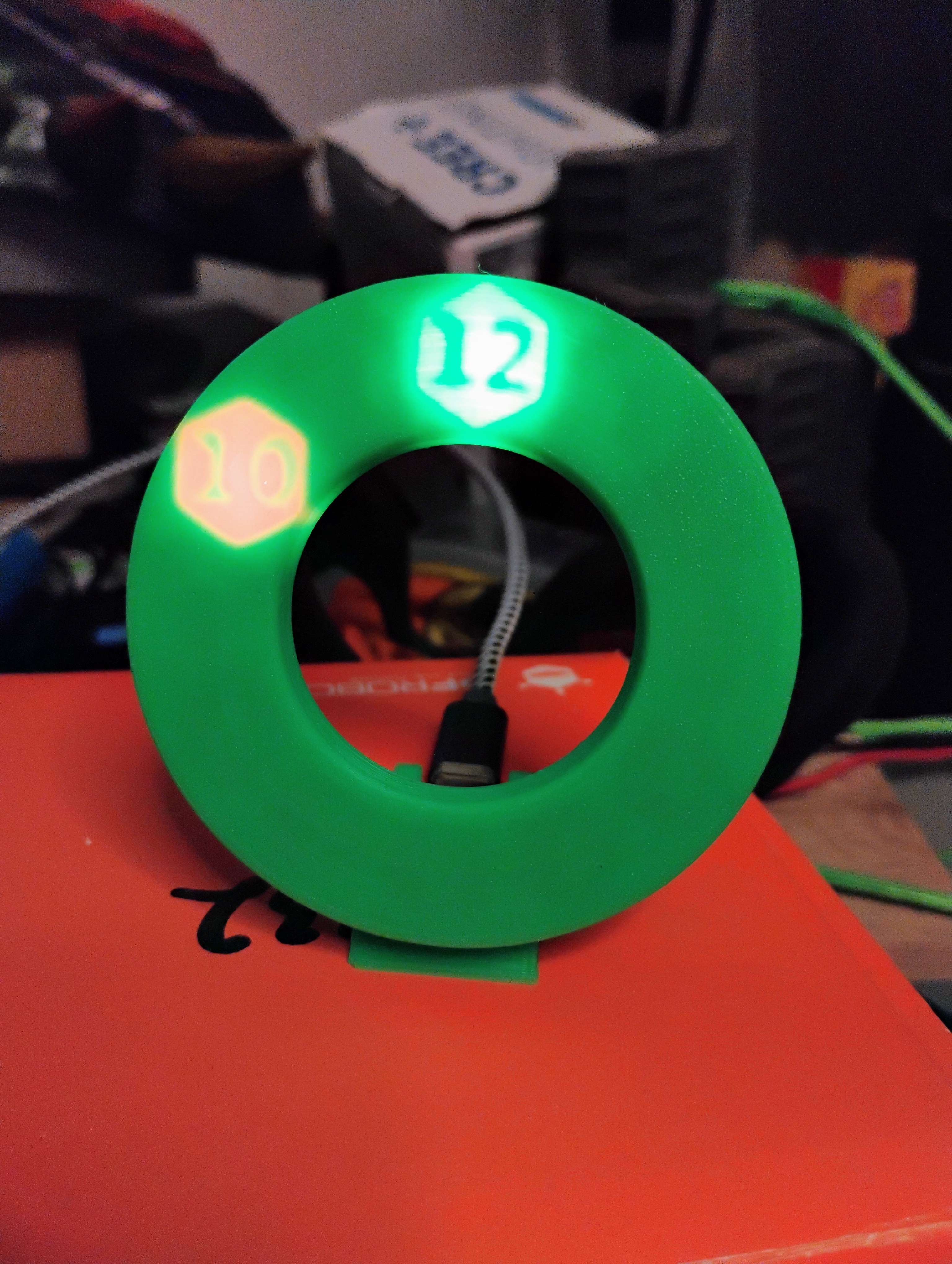
This is a project to build clock. Driven by a ESP32C3, using a 3D printed light diffuser and a NeoPixel LED ring, this clock will display the hour and minute as shadowed numbers in glowing hexagons.
Working Example!
External Parts
-
24x NeoPixel Ring
- A different ring could be used with if the Clockface Generator Notebook is appropriately configured.
-
QT Py ESP32C3
- Pretty much any of the ESP32 QT Py's could run the firmware since it only needs 2 GPIO and an internal clock
Code Dependencies
Clock Controller
Hidden Clockface Generator
Inspirations
I had been playing with lithophanes a lot (such as those from the Lithophane Maker) and became enamored with how a thick-but-not-too-thick light difuser could cause an image to disappear without a backlight. The effect made static surfaces able to pop with hidden messages. I made some concept pieces out of wood that confirmed the basic idea. And then, toying with a NeoPixel ring one day, the idea of a light diffuser based clock came together.
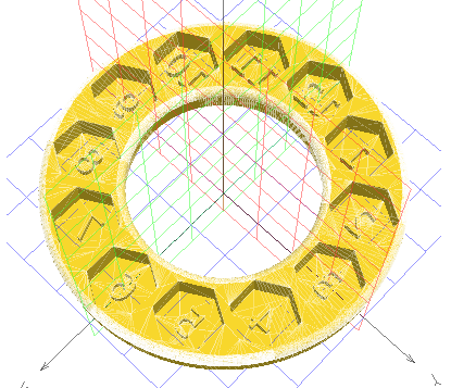
Hidden Clockface Model
Assembly Instructions
- Print Hidden Clockface, Clock Stomach and Embedded Button
- Load clock.upy firmware onto Micropython formatted QT Py ESP32C3
- Solder 3-wire connector cable from 24x NeoPixel Ring to the 5V, GND, and M0 pins of the QT Py ESP32C3
- Guarantee NeoPixel ring works and responds to both short and long button presses.
- Glue 24x NeoPixel Ring to Clock Stomach
- Place QT Py ESP32C3 into Clock Stomach slot and solder-plasticweld the Embedded Button into place -- MINDFUL OF BUTTON PLACEMENT --
- Solder/plasticweld Hidden Clockface to Clock Stomach in front of 24x NeoPixel Ring
Control Instructions
- Short press (<200 milliseconds) adds a 3 minute modifier to the internal time
- Long press (>200 milliseconds) adds a 1 hour modifier to the internal time
-
24x NeoPixel Ring
-
Broken Motion: Replace a PIR Detector Lens The solar-powered security light spent many years in the sun, charging its batteries to protect from the darkness. It is highly valued for its reliable and selfless vigilance. The unit is completely self-contained and requires no electrical wiring. It was perfect for temporarily replacing wired security lights when they were disconnected during a recent house remodeling project. The solar light also spent time strapped to a tree to surprise nocturnal raiders in the garden.
Of course, to work at its peak, the solar charger needs at least 6 hours of direct sunlight to prepare for the next nighttime watch. But after 15 or more years in the sun, the plastic enclosure became yellowed by UV light. That should be an easy fix: apply some masking tape to the passive infrared (PIR) detector lens, LED flood array, and solar cell, then spray on a couple of coats of glossy white paint. All went well until the PIR detector lens was touched. It was very brittle and disintegrated into Fresnel dust.
Sadly, I figured that the lens was unique and manufactured specifically for the PIR detector enclosure of that old light and couldn't be replaced. Oh well, since it was working before, the unit could at least be kept for spare parts.
The Lens is Indeed Unique
The usually flexible frosted plastic detector lens is pretty special. It doesn't just protect the electronics and optics from the weather, it also concentrates and directs IR energy onto the internal thermopile sensor using a custom pattern of refracting grooves (a Fresnel pattern) molded onto one side of the thin plastic. The lens pattern provides greater sensitivity for detecting movement than would be possible through a clear window, increasing the range from 1 meter to almost 15 meters. The lens also concentrates the field-of-view to approximately 120 degrees.

-
SevenSeg: Create an Instrumentation Vibe for Displayio SevenSeg is a CircuitPython displayio -compatible collection of four ultra-compact monospaced
.bdffonts that mimic the look of a seven segment LED display. To keep the font file size small, only the numeric characters that a seven-segment display can represent are included in the font, including uppercase and lowercase hexadecimal. Okay -- there are a couple of other useful things in there, too.Supported characters:
+ - . 0 1 2 3 4 5 6 7 8 9 : A B C D E F _ a b c d e f °
SevenSeg Font GitHub repository

-
Running Two Programs on a Single CircuitPython Device Running Two Programs on a Single CircuitPython Device
I have a nice e-ink display on my shelf running a CircuitPython program that updates the display every fifteen minutes. Recently I wrote a second program that would also just be ideal for this display.
Thinking about my options, I could either
- copy the relevant program to the MCU everytime I want to switch
- write a wrapper application for both programs
The first option was not attractive, because I want to switch on a regular basis. The second option also has it's problems. Both existing programs are valid stand-alone and are maintained in their own Github-repositories, so adding a wrapper would make changes to the software much more complicated.
So I was thinking about a sort of "boot-switcher". Users running Linux on their PCs often have a boot-manager that allows them to switch to more obscure operating systems once in a while, and I wondered if there is a simple way to use this concept also for a CircuitPython device.
Hardware Setup
Since a MCU neither has a BIOS that can start a boot-manager before the real OS, nor (usually) a mouse or keyboard attached for the selection of the target program, this solution needs a free GPIO and a slider or button.
Our "boot-manager" is the code in
boot.py. This code reads the state of the GPIO and starts one of the programs depending on the value. Using a slider will result in a "sticky" behavior: unless you flip it again, each reset will start the same program. The button is different, since you have to keep it pressed during power-on/reset to start the second program. So the second program is more of an exception while the first program runs as the default.Software Setup
For the boot-switcher to work, the programs can't be deployed to the top-level directory of the CIRCUITPY-drive. Instead, the layout on the drive is like this:

So every application moves one level down into its own directory.
You can find the necessary
boot.pyin the Github-repo https://github.com/bablokb/cp-bootswitcher. In this file, you have to configure your setup, e.g.PIN_SWITCH = board.D1 APP_NAMES = ["_app0","_app1"] SHARED_FILES = ["boot.py"]+APP_NAMES
The names of the application directories don't matter, but you have to add the names to
APP_NAMES. You can also add more files/directories toSHARED_FILES, but all of these entries must be top-level. One use case for this is if your applications share the lib-folder.How does it Work?
The implementation of the boot-switcher turned out to be simple and during power-on or reset you won't notice a delay. The code in
boot.pyonly checks the state of the GPIO and then moves all files from the top-level back to the appropriate application folder and then all files from the other application folder to the toplevel. Moving is a fast operation, since it only changes the entry in the directory-table (FAT), so moving a very large lib-folder won't be slower than movingcode.py.Other Use-Cases
There are a number of other use-cases for the boot-switcher, e.g.
- providing two versions of an application, e.g. a beta version in addition to a productive version
- providing a special diagnostic application in addition to the normal application
- running the same application with two different configurations (e.g. within two different WLAN-networks)
- having two sets of libraries e.g. for CP 8.x and 9.x
Final Notes
If you only want to start different top-level programs and otherwise share the rest of your code and all settings, you don't need the boot-switcher. You can do this with a few lines of code, e.g.:
import supervisor
...
supervisor.set_next_code_file("admin.py",sticky_on_reload=True)
supervisor.reload()
Code within
boot.pycan do many things for you. For example, you can make the CIRCUITPY drive writable for your program or hide it for the PC. Of course you can also shoot yourself in the foot, so reading the documentation is recommended. -
Tiny Plaintext MIDI Sequencer for SAMD21 When playing with synthesizer patches, it helps to have a MIDI sequencer to generate note triggers for you. One option is to use a DAW on a laptop, like Ableton or whatever. But, it can also be nice to go DAWless with a hardware sequencer, because buttons and knobs and blinking lights are fun. With DIY sequencer projects in mind, I wrote a plaintext music notation sequencer module for CircuitPython, called txtseq.
The sequencer can read a song from a text file on your CIRCUITPY drive, parse the music notation into an array of MIDI note on and off events, then play the MIDI events in an event loop (allowing time to run other code). The music notation is loosely based on a subset of the abc standard. Notation for note pitch, accidentals, octave, and duration is very similar to abc. For everything else, the sequencer uses a simpler grammar and syntax that is easy to parse on a microcontroller.
CircuitPython + GarageBand Audio Demo
In my GitHub repository for the sequencer, the demonstration track I wrote is named
track1.txt. To hear what the commit 9c73ec4 version oftrack1.txtsounds like when played from a Trinket M0 over USB MIDI into a MIDI drum instrument in GarageBand, you can listen todemos/track1-180bpm.mp3.How to Run the Code
I've been testing this with CircuitPython 9.0.5 on a Trinket M0 (SAMD21), but most of the code (all but MIDI out) also runs on desktop python3.
CircuitPython Version
Prepare a host computer with something that can play sounds for incoming USB MIDI notes on channels 10, 11, 12, and 13. For example, on macOS, you can use the GarageBand app by adding a MIDI track to an empty project, then selecting a drum kit as the MIDI track's instrument.
Update CircuitPython and bootloader the normal way. (no additional libraries are needed)
Fetch a local copy of txtseq using
git cloneor by downloading a release archive.Copy the
txtseq/txtseqdirectory to your CIRCUITPY drive (see docs at Welcome to CircuitPython! > The CIRCUITPY Drive)Copy
txtseq/code.py,txtseq/boot.py, andtxtseq/track1.txtto your CIRCUITPY drive
When
code.pyruns, it will parse music notation fromtrack1.txtinto an array of MIDI note event data, then start playing the notes over USB MIDI. The parser and playback code print a variety of debug info to the serial console to help with measuring memory and CPU use along with MIDI playback latency.Desktop Version
This will give debug prints only, without actual MIDI playback. But, you could easily modify the code to use a library that is capable of sending MIDI. (see definition of
midi_tx(data)callback function intxtseq/__main__.py)Clone the txtseq repo
cd txtseqpython3 -m txtseq track1.txt
Example Output
This is from running
code.pyon a Trinket M0 with CircuitPython 9.0.5:10: ppb=4 11: bpm=180 19: 1 ................ 20: 1 ................... 21: 1 ............................... 22: 1 ................ 23: 1 ................... 24: 1 ...................... [parse time: 517 ms] 00009924 00078924 0010992A 0017892A 00189924 001F8924 0028992E 002F892E 00309928 00378928 0040992A 0047892A 00489924 004F8924 0058992E 005F892E 00609924 00678924 0070992A 0077892A 00789924 007F8924 0088992E 008F892E 00909928 00978928 00A0992A 00A7892A 00A89924 00AF8924 00B8992E 00BF892E 00C09924 00C78924 00D0992A 00D7892A 00D89924 00DF8924 00E8992E 00EF892E 00F09928 00F78928 0100992A 0107892A 01089924 010F8924 0118992E 011F892E 01209924 0120992E 01278924 0127892E 0128992A 012F892A 0130992E 0137892E 01389924 013F8924 0140992E 0147892E 0148992A 014F892A 01509928 01578928 0160992A 0167892A 01689924 016F8924 01789924 017F8924 01809924 01838924 01849924 01878924 01889924 018B8924 018C9924 018F8924 01909924 01938924 01949924 01978924 01989924 019B8924 019C9924 019F8924 01A09924 01A38924 01A49924 01A78924 01A89924 01AB8924 01B09933 01B38933 01B49933 01B78933 01B89933 01BB8933 01BC9933 01BF8933 01C09933 01C38933 01C49933 01C78933 01C89933 01CB8933 01CC9933 01CF8933 01D09933 01D38933 01D49933 01D78933 01DC9924 01DF8924 01E09924 01E38924 01E49924 01E78924 01E89924 01EB8924 01EC9924 01EF8924 01F09924 01F38924 01F49924 01F78924 01F89924 01FB8924 01FC9924 01FF8924 02049931 020F8931 02109924 02178924 0220992A 0227892A 02289924 022F8924 0238992E 023F892E 02409928 02478928 0250992A 0257892A 02589924 025F8924 0268992E 026F892E 02709924 02778924 0280992A 0287892A 02889924 028F8924 0298992E 029F892E 02A09928 02A78928 02B0992A 02B7892A 02B89924 02BF8924 02C8992E 02CF892E 02D09924 02D78924 02E0992A 02E7892A 02E89924 02EF8924 02F8992E 02FF892E 03009928 03078928 0310992A 0317892A 03189924 031F8924 0328992E 032F892E 03309924 0330992E 03378924 0337892E 0338992A 033F892A 0340992E 0347892E 03489924 034F8924 0350992E 0357892E 0358992A 035F892A 03609928 03678928 0370992A 0377892A 03789924 037F8924 03889924 038F8924 03909924 03938924 03949924 03978924 03989924 039B8924 039C9924 039F8924 03A09924 03A38924 03A49924 03A78924 03A89924 03AB8924 03AC9924 03AF8924 03B09924 03B38924 03B49924 03B78924 03B89924 03BB8924 03C09933 03C38933 03C49933 03C78933 03C89933 03CB8933 03CC9933 03CF8933 03D09933 03D38933 03D49933 03D78933 03D89933 03DB8933 03DC9933 03DF8933 03E09933 03E38933 03E49933 03E78933 03F09931 03FB8931 [midi event dump time: 191 ms] mem_free: 10976 10880 9728 diffs: 96 1152 Playing on USB MIDI ch10-13... Done
The top section has debug print output from the parsing functions.
The second section is a dump of the array of timestamped midi events created by the note parsing code.
The third section summarizes
mem_free()measurements. (seecode.py)The last section has debug prints from the MIDI event player.
Reading the Code
This section is for people who are interested in how the sequencer works. It's kind of technical, and I used a variety of optimization tricks to get it to fit and run well on a non-Express SAMD21 board.
The txtseq module exports a function,
sequencer(f)(seetxtseq/sequencer.py) which expects its argument,f, to be a binary mode file object (e.g.open('some-song.txt', 'rb')). For usage examples, seecode.pyortxtseq/__main__.py.The
seqencer()function parses its input file to find top level commands, which it then uses to call further parsing functions. For example, the commands1,2,3, and4call thep_staff()function defined intxtseq/staff.py. The numbers correspond to each of the four voices (tracks). Note on and off events generated by the parser get packed as uint32 values in anarray.array('L'). The most significant 16 bits have a timestamp (units of MIDI pulses). The low 16 bits have MIDI status and data bytes. This allows for adding note events one voice at a time without worrying about out-of-order events. I sort the array at the end to merge all the events from different voices into one list ordered by ascending timestamps.To get all the parser code to compile and run on a SAMD21, the module is split into several files of less than 150 lines each. Also, I used several MicroPython optimization techniques from Damien George's 2018 PyCon AU talk, "Writing fast and efficient MicroPython".
The
txtseq/util.pyfile holds parsing functions for dealing with comments (# ...), semantically irrelevant whitespace, and setting of header options (Bfor bpm,Ufor time unit)Parsing of note pitch and duration for staff lines happens in the
p_staff()function oftxtseq/staff.py. The parsing style is based on state machine loops that examine one byte at a time, reading bytes withreadinto()to limit heap allocations. When one of the parser functions or state machine branches recognizes a byte that should be processed by a different function or state branch, it will rewind the file's cursor position by one byte using thef.seek(mark)idiom.Playback uses a generator defined in
txtseq/player.py. By using the generator as the iterator for an event loop, it's easy to run your own code interleaved with the MIDI player (seemain()incode.py). Also, holding playback state in the local scope of a generator makes it possible to avoid many heap allocations and dictionary lookups that would add jitter and latency if the MIDI player used a class instance.
Music Notation Grammar and Syntax
This section is for people who want to write songs for the sequencer to play as MIDI events.
For examples of how the plaintext music notation works, check out the comments in
txtseq/track1.txt.The ASCII note transcription style used here is loosely based on the abc music standard, but the two notations are not compatible. In particular, this notation uses
{}for chords, requires chord durations to be specified after the closing}, and omits a lot of abc's features such as configurable key signature.The short summary:
Single note:
<accidental><pitch><octave><duration>(e.g.C_B,c2)Rest:
z<duration>(e.g.zz2z16)Chord note:
<accidental><pitch><octave>Chord:
{<chord note><chord note>...}<duration>(e.g.{C^DA}4{ceg})Accidental:
_(flat),^(sharp), or the empty string (natural)Note:
C D E F G A B c d e f g a b(Cis middle-c,cis 1 octave up)Note aliases: you can use some shorter aliases to write percussion parts:
hfor^F _G(closed hi-hat),Hfor_B ^A(open hi-hat), andrfor_e ^d(ride cymbal)Octave:
,(lower by 1 octave),'(raise by one octave), repeated commas or single-quotes are cumulative (,,lowers 2 octaves,'''raises by 3). Examples:C,,,d'Duration: An integer representing the length of a note or chord as a multiple of the current time unit. Duration is optional with a default value of 1. With the time unit set for
1/8,C2would mean a quarter note of middle-c, andCwould be an eighth note.Staff: staff lines start with a voice number then have an arbitrary sequence of whitespace, bar lines (
|), notes, and chords. Bar lines and whitespace are ignored by the parser, but you can use them to help organize your notes for better readability. It's fine to make long notes that last for more than one measure (e.g.C,16with time unit set to1/8would be played the same as 2 tied whole notes in 4/4 time)
Example:
2 | {CDG}4 {ACD}4 | C2 C2 D2 G2 |For more examples, see
txtseq/track1.txtSetting BPM and Time Unit
The
Bcommand sets bpm, which is a global setting that gets applied during playback. For example, a line withB 120would set the playback speed to 120 beats per minute.The
Ucommand sets the time unit, which relates to the duration numbers. For example, You can set the time unit to 1 eighth note withU 1/8command. In that case, if you wroteC2in a staff, that note's duration would be 2 eighth notes (1 quarter note). Or, for quarter note triplets, you could use theU 1/4Tcommand. In that case, the duration of aC2would be 2/3 of one quarter note.The time unit options are:
1/4,1/8,1/16,1/32,1/4T,1/8T,1/16T, and1/32TBass Clef Percussion Notes on Voice 1
The General MIDI standard includes a mapping of percussion sounds for MIDI channel 10, notes 35 to 81. The sounds for a typical Western drum kit (kick, snare, hi-hat, cymbal, etc) use notes in the bass clef, starting approximately 2 octaves below middle C. To avoid having to write things like
B,,,orC,,every time you want a kick drum, voice 1 uses bass clef note names.Bass clef note names are 2 octaves (24 MIDI notes) lower than the equivalent treble clef note names. So, bass clef
Cis the same MIDI note asC,,in treble clef.Also, because the hi-hats and ride cymbal would otherwise need to be spelled with a flat or sharp prefix, I included the aliases
h,H, andr. For quick reference, these are the notes for some common drum sounds:Bass Note MIDI # Sound C 36 Electric Bass Drum E 40 Electric Snare ^F _G h 42 Closed Hi-Hat _B ^A H 46 Open Hi-Hat _e ^d r 51 Ride Cymbal Priority Scheduling of MIDI Messages
For a MIDI link that can move 1 message per 1 ms, playing a chord of 3 notes would take 3 ms to send. If the chord was meant to play on the same beat as a drum strike and a CC update, the whole group would take 5 ms to send. But, if the drum messages get sent first, the timing will sound tighter.
Considering that low latency matters more for percussion, giving scheduling priority to messages for the percussion (usually MIDI channel 10) should help to make the most of available MIDI bandwidth.
To allow for efficient percussion-priority sorting of MIDI events, I hardcoded the player to use the following txtseq voice to MIDI channel mapping:
voice MIDI channel Scheduling Priority 1 10 1 2 11 2 3 12 3 4 13 4 -
Magicquest! Revisiting some of my Neo Trinkey experiments, I've been modifying code that no longer works with CircuitPython 9.x. This is another story generator I created using names and items generated with fantasynamegenerators.com.
Like "Tell me a story, Neo Trinkey" you get random stories by touching tab #2. Tab #1 chooses the hero name, class and race.
The repository is here
and includes
- magicquest.py - program file, rename to code.py
- prt.py - helper file for prt("text",REPL) function. REPL=True to send output to REPL and False for keystroke output
Data files for story input :
- destination.mq
- enemy.mq
- forest.mq
- names.mq
- treasure.mq
- weapon.mq
Load these on your NeoTrinkey and you can get stories like this:
The dwarf burglar Polo Littlefoot
gets lost at
Corftey Fortress
discovering Black Magic Tome
Polo Littlefoot is surprised when The Black-Eyed Cinder Spider attacks from Jagged Covert
Stumbling badly, Polo Littlefoot somehow manages to find the Mournblade, Gift of Ancient Power and dispatch them!
No, not great literature, but I had fun creating it!
note: illustration above from
https://www.publicdomainpictures.net/pictures/190000/velka/medieval-fantasy-castle-2.jpg

-
Raspberry Pi Pico Dice Programmed with CircuitPython Some design notes:
- The top of the cube (yellow, top facing down) has a bevel. This matches the:
- LED top section (pink) bevel - this keeps the top from sliding through the outer cube.
- The bottom layer of the bottom section (tan) is about 4mm thick. The switches are about 4mm tall, so they would be flush with the bottom, except in order to make one switch more prominent (the power switch) I carved out about 1mm so that switch protrudes about 1mm below the bottom.
- There is a box just large enough to squeeze in the battery holder keeping it firmly in the place in the assembled cube.
- On the outside of the battery holder box is a shallow half-box which supports the Pico vertically, with the USB facing downward. The box is about 5mm wider than the Pico itself so there is room for the wiring to extend bast the edge of the board connected to the GPIO pins. The wired Pico is hot-glued to the support plate to keep it firmly in place when connecting a USB cable.
- There is also 4mm groove in the base to allow the Pico's USB port to sit only 1mm above the bottom so a cable can be plugged in the assembled cube for updating the code without having to disassemble the cube.
3D Case Design
I used TinkerCad (https://www.tinkercad.com) for my 3D design work. The original thought was to make two halves - a top and bottom that overlap/slide together. but I ran into some difficulties with this design. Ultimately, I broke it down into 3 parts - an outer 70x70x85mm cube with a 50mm square "hole" through the middle. Then I made two 50mm cubes for the top and bottom that mate open end to open end and slide into center of the cube. The heights of each are one half the depth of the cube so when assembled the closed ends are flush with the top and bottom of the cube. The top has the 9 holes which just fit the 10mm LEDs. The bottom had places to support the Pico and battery back with cut-outs for the slide switches and the USB connector on the Pico.
Here are what the three parts look like in TinkerCad:


