Getting Started

Adafruit Playground is a wonderful and safe place to share your interests with Adafruit's vibrant community of makers and doers. Have a cool project you are working on? Have a bit of code that you think others will find useful? Want to show off your electronics workbench? You have come to the right place.
The goal of Adafruit Playground is to make it as simple as possible to share your work. On the Adafruit Playground users can create Notes. A note is a single-page space where you can document your topic using Adafruit's easy-to-use editor. Notes are like Guides on the Adafruit Learning System but guides are high-fidelity content curated and maintained by Adafuit. Notes are whatever you want them to be. Have fun and be kind.
Click here to learn more about Adafruit Playground and how to get started.
-
🎵️ Media hub 2.0: Media control w/opt Bluetooth Overview
Physical controls for a more enjoyable media playback experience.
Features
- Responsive volume knob & mute button.
- Transport controls (play/pause, stop, FF/REW, skip tracks).
- Pair up with your favourite Bluetooth® speakers.
- Quick, physical connection (don't have to go through menu system to pair with keypad & speakers).
- Customizable controls/scheme.
This project tries to improve over the original "Media hub" presented here.
- More compact design
- Bigger volume knob - not interfering with macropad keys.
🛒️List of main material/hardware
(See section "More tools/materials/hardware" near the end of this note for extras)

-
Rust on the Adafruit Feather RP2350 HSTX Let's start with the Debug Header, the little 3 pin interface lets you peek into the Pons of the Raspberry Pi brain. You can find this header on the Raspberry Pi 5, the Raspberry Pi Pico (H, and WH), and now happily the Adafruit RP23XX boards thus far. By connecting a Pico Probe to this interface, you can get a lot of debug information back on your big main computer. ARM refers to this type of interfacing / debugging as Semihosting.
With the 3-Pin JST cable, cable plugged into the D header on the Pico Probe and the other end of that cable onto the Debug Header on your Feather (Shown above); With the Pico Probe connected to your computer, and you can connect the Feather to any USB power source, or back to your computer as well. Once you've done that, you're ready to issue the
cargo runcommand, so long as you have the required software installed below.Back to the code we cloned all of the way at the top of this article. With all of the software above installed, and your computer connected to the debug probe, the probe connected to the feather, and the feather connected to power or your computer you now have a system that is ready to go. We really can run that
cargo runcommand and have Rust code on our feather. But what are all of these files and what do they do?.cargo/config.tomlandcargo runThe
.cargo/config.tomlfile configurescargo runto useprobe-rsto flash to the boards ROM. You will need a Raspberry Pi Debug Probe in order to use this, but it makes development MUCH easier, faster, and more fun! You connect the Debug Probe'sD(for debug,Dfordefmt😉) side to the board's Debug Port. Once done connect the Adafruit board, and Debug Probe to your computer. You can flash at will withcargo runand see any debug messages in your computer's terminal thanks todefmt.memory.xIf you've never seen a
memory.xfile before, and have no clue what it is; I don't blame you for being curious. It's an odd file, filled with things that aren't Rust or C, or anything else that fits the norm. This file actually tells the linker where to put sections of the binary. It makes sure everything is in order so that when the microcontroller jumps to flash memory, the expected data is there ready for it. It also tells the the linker how much RAM the target board or chip has.build.rsThis build script copies the
memory.xfile from the crate root into a directory where the linker can always find it at build time. For many projects this is optional, as the linker always searches the project root directory -- whereverCargo.tomlis. However, if you are using a workspace or have a more complicated build setup, this build script becomes required. Additionally, by requesting that Cargo re-run the build script whenevermemory.xis changed, updatingmemory.xensures a rebuild of the application with the new memory settings.
-
Zephyr Quest: IoT Toggle Switch for Feather TFT This guide shows how to make an IoT toggle switch with an Adafruit Feather TFT ESP32-S3, Zephyr, and Adafruit IO. Key features include: GPIO input for Boot button, LVGL graphics, MQTT over WiFi with TLSv1.2, and USB serial shell commands for saving WiFi and MQTT configuration settings to NVM flash. This guide is intended for people who want to learn how to write applications in C using Zephyr APIs.
Demo video: IoT toggle switch: Zephyr + Feather TFT + Adafruit IO
Previously in this series of guides about using Zephyr on Adafruit hardware, I focused on setting up developer tools and writing Devicetree board definitions. This time, I'm moving up the stack to show how to build an application tying together several Zephyr APIs along with a custom board definition.
Building an IoT app with WiFi, TLS, and graphics is unavoidably a bit complicated. It took me about three weeks to write the code, which totals a bit over 2100 lines. Listing all of that here would be awkward. If you want the details, you can browse the code in my zphqst-03 GitHub repo. The code has lots of comments, including citations for the references I used while learning to use the Zephyr APIs.
This guide will focus on:
- How to build, run, and configure the IoT toggle switch app
- High level tour of the source code with GitHub links: which files do what?
- Understanding C language features that you'll need to use Zephyr APIs effectively: structs, function pointers, etc.
- Zephyr troubleshooting tips: diagnose and fix memory allocation issues, enable various types of debug logging, etc.
- MQTT testing with
openssland themosquittoMQTT broker with its companion command line tools,mosquitto_pubandmosquitto_sub

-
No-Code Easy Ambient Smart Lights Overview
With all the newest features of Adafruit IO, WipperSnapper firmware, and the new Blockly Actions, you can create really complex projects without writing a single line of code. I've been working on a couple versions of smart lights to notify me of different things using NeoPixels. This project will focus on a super easy smart ambient lighting system that you can stick to the back of your computer monitor.
Components
Using just a few Adafruit components is all you need to create a really simple, but pretty powerful little notification system. We are gonna use a QT Py ESP32-S2 WiFi Dev Board to talk to Adafruit IO, a NeoPixel BFF for the QT Py, and finally a short NeoPixel strip with a JST connector pre-attached (so you can connect right up to the BFF board.
The only soldering you will need to do is to attach the boards together. You can solder the boards together with the included pins, or pick up some female headers so you can detach the boards and use them on any future projects.

-
CircuitPython "Avalanche Noise" RNG with TPS65131 & NPN transistors I've long had an interest in random number generation. In fact, a very early PCB I designed and built was exactly for this purpose: Arduino Random Number Generator.
That project used a property of transistors called "avalanche noise". Inconveniently, it required a supply of +-10V to work properly. Avalanche noise is sometimes explained as being a "quantum effect" and thus is supposed to be a source of true randomness.
When the TPS65131 went into the store, I knew it was time to revisit this project. This little PCB generates positive and negative voltages from a single +5V input.
Parts

-
3D printed Bracket for 4 64x64 2mm RGB matrix panels I wanted to assemble four of those 64x64mm RGB matrix panels. However, my 3D printer is limited to about 250x205mm, and the panels are 256x256mm.
It required a little creativity, but I devised a single print of about 249x136mm such that by printing two and flipping one of them over, it becomes a bracket that can hold the four panels together.
I have a feeling that the injection molded bodies of these panels may change from time to time, potentially moving the screw & post positions. My 4 panels were purchased around February 2025.
I developed the part in OpenSCAD, Free (GPL) 3D modeling software available on Linux, Mac, & Windows. To create a 3D printable STL file, open the SCAD file, press F5 to "render" it to triangles, and then F7 to export to STL.

-
Universal BLE Remote with Keyboard Featherwing Overview
One of the coolest things about Solder Party's Keyboard Featherwing is its versatility. While it offers a fully-featured hardware package all on its own, the ability to pair it with any Feather board allows it to be extended to do pretty incredible things. In this project, I'm pairing it with a Feather nRF52840 Express to create a universal Bluetooth Low Energy (BLE) keyboard/mouse/remote control, programmed in CircuitPython.
Using the nRF52840, CircuitPython has the ability to send BLE keyboard, mouse, and consumer control HID events to control a host device, such as a computer. This firmware combines the ability to send all 3 event types from a single device in an easily configurable way, adding another layer of versatility!
Some possible applications:
- Control a laptop connected to a TV remotely, with physical keyboard and full mouse support
- Control an Apple TV, including navigation. Use a physical keyboard when searching!
- Remotely trigger the camera shutter on iPhone/iPad
- Use the 9 programmable buttons to make a BLE "macro pad"
- Practically anything that could benefit from a BLE keyboard, mouse, and/or consumer control remote
Another nice thing about the nRF52840 for this application is its excellent energy efficiency. When using a 2000mAh LiPo battery, I've been able to get between 70-80 hours of active use on a single charge! The Keyboard Featherwing's built-in on/off switch allows extending the battery life even further.
Firmware Features
- Compact physical keyboard makes it easy to type wirelessly on device like laptops/desktops, Raspberry Pis, or anything else that can connect to BLE keyboards.
- Touch screen behaves as a trackpad/mouse when connected to a host device that supports pointer devices.
- 4 activity presets, selectable through an on-screen preferences menu. Further configuration is possible by connecting device to a computer via USB and editing the configuration files in the user directory.
- Each activity allows you to customize the 4 function buttons and the 5-way direction button (D-BUTTON) to send keyboard, consumer control, and mouse button events
- Adjustable display/keyboard/NeoPixel brightness
- Adjustable primary user interface color
- Power-saving feature: auto-dim keyboard, screen, and NeoPixel after 30 seconds of inactivity, significantly increasing battery life.
- Battery voltage monitoring and "needs charge" indicator.

-
Monitor Indoor Air Quality with Blues, IFTTT, Adafruit IO and a Hue LED Strip If you're working an office job, you're...in an office. Whether that's in your home or not, I'm going to hazard a guess that it's also indoors - and being indoors for an extended period of time without well-ventilated spaces can legitimately lead to low air quality (and in theory health issues).
Now, I'm not hear to spread fear and make you all think you're dying a slow death by breathing in your co-worker's exhalations. However, I am here to show off an easy way to build a cloud-connected indoor air quality system with:
- A variety of Adafruit air quality sensors.
- A Blues Notecard to cloud-connect the project with LTE connectivity.
- Adafruit IO to visualize air quality data and integrate with other services.
- A Philips Hue LED strip to provide real-time visuals for low air quality alerts.

-
A Node Based CAD Add-in for Fusion 360 Gradient is a node-based editor designed for use with Autodesk Fusion 360.
I started working on Gradient after playing with the node based geometry in Blender. The nodes in Blender are fantastic (frankly they work much better than mine do right now) but I wanted to create algorithmically defined geometry right in Fusion 360 using solids and surfaces which are better suited to making 3D models for technical and engineering parts. I wanted to be able to make algorithemic structures that are user defined but and can be finely controlled and tuned to the design needs.
Models like this would be very time consuming to model by hand. However they can be quickly generated and re-generated with different parameters or random seeds.
If you are interested in trying Gradient for yourself you can download it from the github repository below. Please be aware currently Gradient is in an early development stage, meaning only a small fraction of its functionality has been implemented, and there are likely a few bugs to sort through.

-
C3P0, Take the Wheel! I really enjoyed getting my first PyBadge because it gave me a way to make my own arcade games using https://arcade.makecode.com. I did find that, I actually like making the games even more than playing them, so I thought about ways to have someone (or something) else play the game.
I'd heard about the idea of "mouse jigglers" - mechanical or software cheats to make it look like you were busy working on a computer when you weren't, and I knew CircuitPython supported HID (Human Interface Device) so I could send keystrokes. So why not "let C3P0 take the wheel"?
That led to my simple "mouse jiggler" for playing arcade games in a browser. (https://en.wikipedia.org/wiki/Mouse_jiggler) (Yes, this actually is a keyboard jiggler that randomly "fires" by sending spaces, and maneuvers by randomly sending cursor keys up, down, left and right.)
Designed to take over playing a simple arcade game in a browser, for example: https://makecode.com/_JfAKKf2EUcLv This game lets you steer the Millenium Falcon, and shoot asteroids and Star Destroyers.
Touch #1 on the NeoTrinkey to fire lasers, and touch #2 to toggle on/off a random "jiggler" that continuosly moves the ship around, randomly shooting.
Touch #1 and #2 together to end program.
Flashes green when autopilot is engaged, and red when it ends. Ending program flashes gold.
Program file:
AutoPilot.py - copy to code.py on the neotrinkey.
Github repo HERE
IMPORTANT NOTE: Programming something like this, using the HID interface can be tricky, as having a program randomly spewing spaces, and cursor keys will mangle any text you are editing. When I wrote this, the initial testing had touching #2 just call the jiggle() function. That way I didn't have a program going crazy and messing with the program text. Once it was working, it was safe to build the loop that would continuously call jiggle() and shoot().
C3P0 accidently piloting the Starspeeder in Star Tours -
Digital Clock with WiFi and Weather (Huzzah & 128x64OLED) I had an Adafruit Huzzah and an OLED FeatherWing 128 x 64 in my box of goodies and decided to make a smart digital clock for my study.
The clock is connected to internet via WiFi, synchronises the time and via an api displays the temperature in my area. It is set to update every 5 minutes. Also displays an icon of the current weather.
These are parsed from the api response:
{"coord":{"lon":yyyyyy,"lat":xxxxx},"weather":[{"id":800,"main":"Clear","description":"clear sky","icon":"01n"}],"base":"stations","main":{"temp":1.03,"feels_like":-1.33,"temp_min":0.57,"temp_max":2.64,"pressure":1039,"humidity":76,"sea_level":1039,"grnd_level":1034},"visibility":10000,"wind":{"speed":2.06,"deg":170},"clouds":{"all":0},"dt":1738790391,"sys":{"type":1,"id":1440,"country":"GB","sunrise":1738742403,"sunset":1738773892},"timezone":0,"id":3333224,"name":"xxxxxx City","cod":200}Next I created a 3D printed bezel that allowed me to fit the stacked boards in my workbench pannel.

-
Zephyr Quest: ST7789 Display with Feather RP2350 As part of a series on Zephyr with Adafruit hardware, this guide shows how to configure Zephyr to use an ST7789 TFT display with a Feather RP2350. By connecting the display with a breadboard, we can use a logic analyzer to verify that the Zephyr display driver pin configuration agrees with the CircuitPython display driver. This guide is meant for people interested in adding support for Adafruit displays to Zephyr.
Parts

-
jq - now as a webservice! 🌍🎣🕸️ Filtering large JSON data jq for all...?
If you've not heard of or used `jq`, then count yourself lucky, as it is the tool of choice for data scientists up a creek with no paddle... If you find yourself wresting a 2GB JSON file then you'll probably end up using jq to help. See more details of the jq command-line tool at https://jqlang.org/Using jq can be really quick and simple, but sometimes finding the right incantation to return a subset of the data can leave you feeling a bit like you've been learning FFMPEG (another great tool where I found myself deep in a tutorial one weekend).
Don't do it yourself, get AI to write that query!
Fortunately we live in the days of Large Language Models ("AI" LLMs), which like nothing more than answering humans need for the correct FFMPEG/jq arguments to solve some "critical" problem.
So don't feel like you need to learn the syntax, just throw your data and desired output format at the machines and ask for the jq syntax to achieve that!Here's an example where I threw a slightly truncated version of the 80kb json at chatGPT and asked for the output format I wanted: https://chatgpt.com/share/67c1c7a6-bf5c-8000-823c-d422593d2ed8
There's also a jq playground website, allowing you to submit your JSON and "query" or fetch the data from a website URL, and it runs entirely in the browser (WASM version of jq) at https://play.jqlang.org/
It's great, but not what I was looking for... I needed something that would allow a microcontroller with very little RAM (random access memory) to get some values from large JSON payloads, without having to download and process all the JSON data just to find a couple of values.
Microcontrollers are usually too underpowered to load a full web browser with javascript and WASM support, so ideally we need something more like a web-service that would allow a simple web request to trigger all the work and return the subset of data we're looking for.

-
Piece Of Pi with a NeoTrinkey! Estimate Pi with the Monte Carlo method and a neotrinkey
The power of randomness can be harnessed! Estimating the area of a circle by throwing darts at random gives you the means to estimate the value of Pi! I first learned about using the Monte Carlo back in the '80's and even used it in software development to estimate timing of events. You can use it with you NeoTrinkey to estimate the valueof Pi. You can find my github repository here: https://github.com/mrklingon/PieceOfPi/
Monte Carlo methods are a broad class of computational algorithms that rely on repeated random sampling to obtain numerical results. One of the basic examples of getting started with the Monte Carlo algorithm is the estimation of Pi. (https://www.geeksforgeeks.org/estimating-value-pi-using-monte-carlo/)
This project iterates over a unit circle of radius one and "throws" darts at random from -1 to 1 x, and -1 to 1 y, then counts how many land IN the circle. Pi is estimated by multiplying 4 * "darts inside circle"/all darts thrown
The more iterations (darts) thrown, the closer you approach the value of Pi.
The program runs continuously, pausing 5 seconds between runs. While the program is running/estimating, the neopixels flash random colors. When it finishes an estimate, the neopixel displays the answer by blinking the neopixels green for the value (three times for three, one time for one and so on.). Zeroes are indicated by turning all pixels pink briefly. The pixels flash blue to indicate the decimal point.
If the program is run inside a REPL like Mu, it will print out the results:
 I will estimate Pi.
it is around : 3.14139
I will estimate Pi.
it is around : 3.13818
I will estimate Pi.
it is around : 3.13422
I will estimate Pi.
it is around : 3.1313
The default value of Iterations is 100 - you can change that to higher or lower values.
Files
- findPi.py - copy to code.py to run
- ncount.py - helper file, provides color definitions and blinknum() to blink the digit values.
For more about the Monte Carlo Method: https://en.wikipedia.org/wiki/Monte_Carlo_method
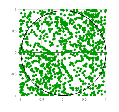 Random points are generated only few of which lie outside the imaginary circle
 -
supervisor.runtime.display in CircuitPython 9.2.5+ CircuitPython 9.2.5 adds a new property to the supervisor Runtime object,
display.If your board has a built in display that is automatically configured by the CircuitPython core (e.g., boards like the Feather ESP32-S3 Reverse TFT), then this display is available as
supervisor.runtime.displayin addition toboard.DISPLAY.So what's different about the new
supervisor.runtime.display?- This property is available on all boards that support
displayio, not just boards with built in displays - Unlike
board.DISPLAY, this property is settable, and remembers its value after your code file finishes running. This means you can set this property once in boot.py and then use the display each time yourcode.pyruns, or re-use a display set by a previous run of code.py. - Due to technical limitations in CircuitPython, when a display is released,
board.DISPLAYbecomes a "None-like object": one that prints asNonebut fails the checkboard.DISPLAY is None.supervisor.runtime.display is Noneworks correctly to check whether a default display is configured.
Setting
supervisor.runtime.displayThere are two approaches:
- Do it unconditionally in boot.py and depend on this in code.py
- Do it conditionally in code.py, if
supervisor.runtime.display is None
... in boot.py
Here's a code snippet that shows configuring a 240x240 ST7789 display connected to an EyeSpi BFF on a QT Py board like the QT Py RP2040:
- This property is available on all boards that support


