Getting Started

Adafruit Playground is a wonderful and safe place to share your interests with Adafruit's vibrant community of makers and doers. Have a cool project you are working on? Have a bit of code that you think others will find useful? Want to show off your electronics workbench? You have come to the right place.
The goal of Adafruit Playground is to make it as simple as possible to share your work. On the Adafruit Playground users can create Notes. A note is a single-page space where you can document your topic using Adafruit's easy-to-use editor. Notes are like Guides on the Adafruit Learning System but guides are high-fidelity content curated and maintained by Adafuit. Notes are whatever you want them to be. Have fun and be kind.
Click here to learn more about Adafruit Playground and how to get started.
-
Magnetometer - MMC5603 to measure gas usage inside your home with home assistant I wanted to measure the gas usage inside my home and push the data into Home Assistant.
To collect the data, I wanted to use the MMC5603 magnetometer + ESP32 Feather V2. The MMC5603 had a great price point and the ESP32 Feather V2 was able to connect to my Home Assistant server via WiFi.
Requirements
- ESPHome 2025.8.3
- The Adafruit Products above (MMC5603 + ESP32 Feather V2 or similar board that can connect via WiFi)
- Ethernet Cable (Cat 5 and later is fine)
- USB Power Adapter (e.g. like this one , 5V 1A)
- A short USB-A to USB-C connector (e.g. like this one, data isn't important here - so any cable will do)
- M2.5 screws (lengths and materials will be up to you, I used nylon M2.5 screws to attach the bracket to the gas meter and metal M2.5 screws for the MMC5603 to the bracket).
If you end up using any earlier version of ESPHome and you'll run into issues like I did where the MMC5603 wasn't being registered properly.
I connected everything like this diagram:
I ended up having to create a 3D bracket that could hold the MMC5603 onto the US Gas Meter.
https://www.printables.com/model/1446364-us-gas-meter-brace-for-a-mmc5603-magnetometer
-
Your own TTS engine for the Fruit Jam Spell Jam app Overview
The Spell Jam app on the Fruit Jam is a twist on a classic electronic toy. Check out the Spell Jam learn guide to learn all about it.
By default, Spell Jam uses the Amazon Polly Text-to-Speech (TTS) service to create audio from the entered text. While Amazon's service can be used for free during a trial period, it does require an AWS account.
If you'd prefer not to create an Amazon AWS account, you can instead run a local TTS server on your home network using open-source models like KittenTTS, Kani-TTS or eSpeak.
This playground will walk you through the steps required to run a local TTS server on your network and configure Spell Jam on your Fruit Jam to use that server instead of AWS.
Installing a Text-to-Speech Model
There are two TTS AI models that the Spell Jam local backend works with:
- KittenTTS - lightweight, will run on a Raspberry Pi 4/5
- Kani-TTS - newer, but may require an Nvidia GPU. (as of 2/2026 Kani no longer works with server.py)
Legacy software TTS application:
- eSpeak - Initially released in 2006, a free and open-source compact speech synthesizer.
Before install any of the TTS systems, create and/or activate a dedicated Python virtual environment.
python3 -m venv venv
source venv/bin/activate
-
How to "wire-up" anything (e.g. a featherwing Display) on WipperSnapper WipperSnapper is a firmware (Arduino sketch) that connects boards with Components + Sensors in a no-code way. It's meant to be easy for beginners to start making things online quickly and simply, but sometimes we forget how much knowledge is expected.
It can be a tall order to know how to find the pin names for each board, but doubly so when you want to connect a seemingly easily sandwiched FeatherWing into the mix.
Today I followed this journey to test a newly supported E-ink FeatherWing display with one of our older boards, the Feather ESP32 v2 (Huzzah32), to replicate the MagTag setup which we know works well.
As I looked for the documentation link in the New Components dialog, I realised this was a step too far for many people to take confidently alone and I should probably document the journey.
Breaking it down

-
Judge Doom Hat – Wearable Monster M4sk Eye Tracking with MPU-6050 Head Control
Hi everyone, just in time for Halloween 👀👁️👁️🎃👻,
I’ve been working on a project that expands the Adafruit MONSTER M4SK – DIY Electronic Eyes Mask (Product ID: 4343) with an Adafruit MPU-6050 6-DoF Accel and Gyro Sensor – STEMMA QT Qwiic (Product ID: 3886) to add head-tracking eye control. The result is the Judge Doom Hat (inspired by Who Framed Roger Rabbit? 🕶️👀).
The focus here is on the code integration: reading quaternion data from the MPU-6050, converting to yaw/pitch, normalizing to eyeTargetX / eyeTargetY, and feeding that into the existing M4_Eyes rendering engine for smooth, natural eye motion.
Features:
🔹Yaw + Pitch tracking — eyes follow head turns and tilts
🔹Quaternion math (Simple_MPU6050.h) — fast, smooth, drift-resistant orientation
🔹Natural movement — eyes decelerate and return to center, no snapping
🔹Stability mode while walking
🔹Tilt-based extras — roll can trigger blinks (backlight off) or switch configs
🔹Configurable ranges — sensitivity, dead zones, and angle limits adjustable
🔹Random wandering disabled — IMU fully drives eye motion
Hardware:
🔹Adafruit MONSTER M4SK – DIY Electronic Eyes Mask
Product ID: 4343
🔹Adafruit MPU-6050 6-DoF Accel and Gyro Sensor – STEMMA QT / Qwiic
Product ID: 3886
🔹Judge Doom Hat – wearable mount
Credits & Acknowledgments:
🔹 (Limor Fried) – Monster M4sk hardware design
🔹Phil Burgess (PaintYourDragon) – Original M4_Eyes eye animation code
🔹Adafruit Learning System Team –
🔹Monster M4sk Augmented Eyes Toon Hat
— starting point for the hat design and graphics
🔹Monster M4sk Is Watching You
— another key starting point we expanded on with the MPU-6050 for natural head-driven eye motion
ChatGPT (OpenAI) – Code structure, quaternion integration, debugging, and iterative design support
Code Files:
This project builds directly on the official M4_Eyes code.
The only files added for the Judge Doom Hat are shown below:
Libraries:
🔹Simple_MPU6050 Library by ZHomeSliceDoomHat.h
user_tracker.cpp
Drop these 2 files into the existing M4_Eyes project folder, disable other user_*.cpp files, and enable user_tracker.cpp. Then upload to your Monster M4sk.
You will need to calibrate the MPU6050 unit first. I used the Simple_MPU6050_Calibration example: https://github.com/ZHomeSlice/Simple_MP ... r/Examples
Future Ideas:
🔹Haptic feedback (Adafruit DRV2605L) — exploring subtle vibration cues for blinks, config switches, or motion events
🔹Peripheral awareness — adding slight eye lag/lead for more lifelike motion
🔹Alternate IMUs (e.g., BNO055, LSM6DSOX) — comparing accuracy and drift over MPU-6050
👁️👁️✨ That’s it!
Looking forward to feedback, code suggestions, and ideas from the community. -
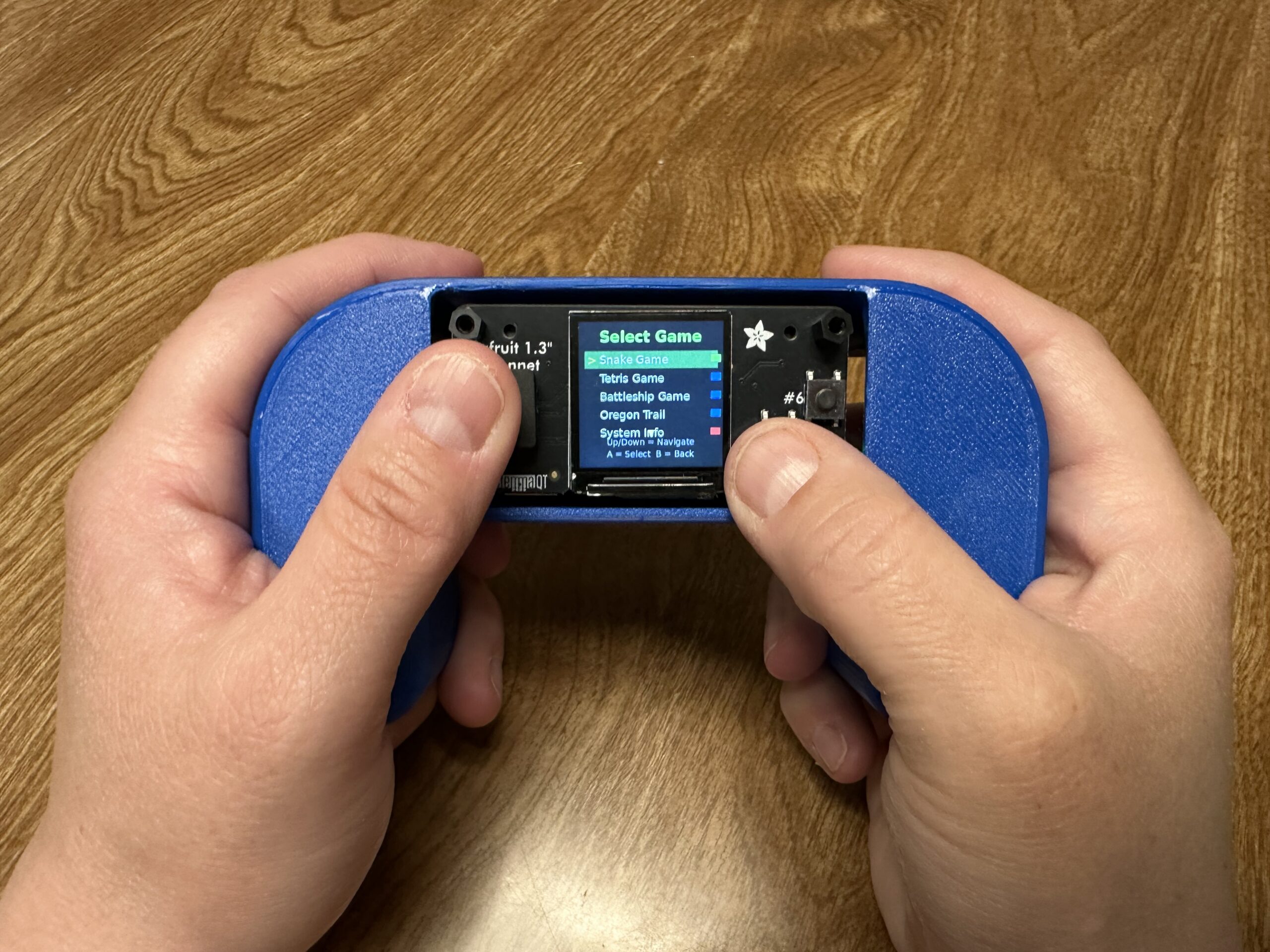
Herman Entertainment System (Pi Zero2w Python Handheld) This is the Herman Entertainment System, a handheld gaming system with a Raspberry Pi Zero 2 W and the Adafruit 1.3″ TFT Bonnet. Why Herman? I don’t know, that is what the kids wanted to call it, apparently Herman needs entertained. As for why we needed this instead of an existing emulator, well this particular setup struggles to run systems like RetroPie due to a display issue, so we created a small setup that uses Python and creates a home screen that lists all the games on the device and you simply choose which to play. It automatically updates with all the games you have added, in our example we have a Snake game, but you can add or make nearly anything. Print files for the enclosure are available here via Printables, and additional details and instructions are available here.
Step 1: Prepare the SD Card (Headless Setup)
Flash Pi OS Lite
- Download Raspberry Pi Imager from raspberrypi.org
- Insert your SD card into your computer
- Open Raspberry Pi Imager
- Choose “Raspberry Pi OS Lite (32-bit)” – no desktop needed
- Click the gear icon (Advanced options) and configure:
- Enable SSH ✓
-
Set username:
herman - Set password: (your choice)
- Configure WiFi: Enter your network name and password
- Set locale settings: Your country/timezone
- Flash the image to SD card
Step 2: First Boot and SSH Connection
- Insert SD card into your Pi Zero 2 W
- Power on the Pi (green LED should flash, then stay solid)
- Wait 2-3 minutes for first boot to complete
-
Find the Pi’s IP address:
- Check your router’s admin page for connected devices
- Or use an IP scanner like Advanced IP Scanner
- Look for device named “raspberrypi”
Connect via SSH
ssh [email protected]
# Replace XXX with your Pi's actual IP address
Enter your password when prompted.
Step 3: System Updates and Basic Setup
# Update the system
sudo apt update && sudo apt upgrade -y

# Install essential packages
sudo apt install python3-pip python3-pil git -y

# Enable SPI (required for TFT display)
sudo raspi-config
In raspi-config:
- Go to Interface Options → SPI → Enable
- Finish and reboot
Reconnect via SSH after reboot.
Step 4: Install TFT Display Libraries
Note: Newer Pi OS versions require
--break-system-packagesflag# Install compatible Adafruit libraries sudo pip3 install "adafruit-circuitpython-rgb-display==3.10.0" --break-system-packages sudo pip3 install "adafruit-circuitpython-busdevice==5.2.0" --break-system-packages sudo pip3 install "adafruit-circuitpython-typing==1.10.1" --break-system-packages # Install additional required libraries for SPI configuration sudo pip3 install click --break-system-packages sudo pip3 install adafruit-python-shell --break-system-packages # Install system packages sudo apt install python3-numpy -y
Step 5: Configure TFT Display Hardware
# Download and run the SPI configuration script
wget https://raw.githubusercontent.com/adafruit/Raspberry-Pi-Installer-Scripts/main/raspi-spi-reassign.py
sudo python3 raspi-spi-reassign.py
When prompted:
- Select 1 Reassign SPI Chip Enable Pins
- For CE0 selection, choose 22 Disabled
- Reboot when prompted
Step 6: Create the Gaming System Files
Reconnect via SSH and create your gaming system:
# Create directories
mkdir -p /home/herman/games
mkdir -p /home/herman/system
Create the main entertainment system:
nano /home/herman/herman_entertainment_system.py

Then copy the following code and paste it into the new file.


#!/usr/bin/env python3
import time
import os
import subprocess
import digitalio
import board
import importlib.util
import sys
from adafruit_rgb_display.rgb import color565
from adafruit_rgb_display import st7789
import RPi.GPIO as GPIO
from PIL import Image, ImageDraw, ImageFont

class HermanEntertainmentSystem:
    def __init__(self):
        # Initialize display and GPIO in the class
        self.setup_hardware()

        # Load fonts
        try:
            self.font_huge = ImageFont.truetype("/usr/share/fonts/truetype/dejavu/DejaVuSans-Bold.ttf", 36)
            self.font_large = ImageFont.truetype("/usr/share/fonts/truetype/dejavu/DejaVuSans-Bold.ttf", 24)
            self.font_medium = ImageFont.truetype("/usr/share/fonts/truetype/dejavu/DejaVuSans.ttf", 18)
            self.font_small = ImageFont.truetype("/usr/share/fonts/truetype/dejavu/DejaVuSans.ttf", 14)
        except:
            self.font_huge = ImageFont.load_default()
            self.font_large = ImageFont.load_default()
            self.font_medium = ImageFont.load_default()
            self.font_small = ImageFont.load_default()

        # Button debouncing
        self.last_button_time = 0
        self.button_debounce = 0.2

        # Game list
        self.games = []
        self.selected_game = 0
        self.games_directory = "/home/herman/games"

        # Create games directory if it doesn't exist
        if not os.path.exists(self.games_directory):
            os.makedirs(self.games_directory)

        self.scan_for_games()

    def setup_hardware(self):
        """Initialize display and GPIO"""
        # TFT Display Setup
        self.cs_pin = digitalio.DigitalInOut(board.CE0)
        self.dc_pin = digitalio.DigitalInOut(board.D25)
        reset_pin = None
        BAUDRATE = 40000000

        self.display = st7789.ST7789(
            board.SPI(),
            cs=self.cs_pin,
            dc=self.dc_pin,
            rst=reset_pin,
            baudrate=BAUDRATE,
            width=240,
            height=240,
            x_offset=0,
            y_offset=80,
            rotation=180,  # Fixed rotation for proper orientation
        )

        self.backlight = digitalio.DigitalInOut(board.D26)
        self.backlight.switch_to_output()
        self.backlight.value = True

        # GPIO Setup - Correct pins for Pi Zero 2 W + TFT Bonnet
        GPIO.setmode(GPIO.BCM)
        GPIO.setup(17, GPIO.IN, pull_up_down=GPIO.PUD_UP)  # UP
        GPIO.setup(22, GPIO.IN, pull_up_down=GPIO.PUD_UP)  # DOWN
        GPIO.setup(27, GPIO.IN, pull_up_down=GPIO.PUD_UP)  # LEFT
        GPIO.setup(23, GPIO.IN, pull_up_down=GPIO.PUD_UP)  # RIGHT
        GPIO.setup(5, GPIO.IN, pull_up_down=GPIO.PUD_UP)   # Button A
        GPIO.setup(6, GPIO.IN, pull_up_down=GPIO.PUD_UP)   # Button B
        GPIO.setup(4, GPIO.IN, pull_up_down=GPIO.PUD_UP)   # Button C


    def get_text_size(self, draw, text, font):
        """Compatible text size function for older PIL versions"""
        try:
            bbox = draw.textbbox((0, 0), text, font=font)
            return bbox[2] - bbox[0], bbox[3] - bbox[1]
        except AttributeError:
            try:
                return draw.textsize(text, font=font)
            except:
                return len(text) * 8, 16

    def draw_centered_text(self, draw, text, y_pos, font, color):
        """Draw text centered horizontally"""
        text_width, text_height = self.get_text_size(draw, text, font)
        x_pos = (240 - text_width) // 2
        draw.text((x_pos, y_pos), text, font=font, fill=color)
        return text_height

    def read_controls_debounced(self):
        """Read controls with debouncing"""
        current_time = time.time()

        raw_controls = {
            'up': not GPIO.input(17),
            'down': not GPIO.input(22),
            'left': not GPIO.input(27),
            'right': not GPIO.input(23),
            'button_a': not GPIO.input(5),
            'button_b': not GPIO.input(6),
            'button_c': not GPIO.input(4)
        }

        # Apply debouncing
        if current_time - self.last_button_time > self.button_debounce:
            if any(raw_controls.values()):
                self.last_button_time = current_time
                return raw_controls

        return {key: False for key in raw_controls}

    def scan_for_games(self):
        """Scan for available game files"""
        self.games = []

        # Add built-in games
        builtin_games = [
            {"name": "Snake Game", "file": "snake_game_module.py", "type": "builtin"},
        ]

        for game in builtin_games:
            if os.path.exists(f"/home/herman/{game['file']}"):
                self.games.append(game)

        # Scan games directory for additional games
        if os.path.exists(self.games_directory):
            for filename in os.listdir(self.games_directory):
                if filename.endswith('.py'):
                    game_name = filename.replace('.py', '').replace('_', ' ').title()
                    self.games.append({
                        "name": game_name,
                        "file": filename,
                        "type": "custom"
                    })

        # Add system options
        self.games.extend([
            {"name": "System Info", "file": None, "type": "system"},
            {"name": "Shutdown", "file": None, "type": "system"}
        ])

        # Reset selection if out of bounds
        if self.selected_game >= len(self.games):
            self.selected_game = 0

    def show_welcome_screen(self):
        """Display welcome screen"""
        image = Image.new('RGB', (240, 240), (0, 0, 50))  # Dark blue background
        draw = ImageDraw.Draw(image)

        # Title with shadow effect
        self.draw_centered_text(draw, "Herman", 31, self.font_huge, (0, 0, 0))  # Shadow
        self.draw_centered_text(draw, "Herman", 30, self.font_huge, (0, 255, 100))  # Main

        self.draw_centered_text(draw, "Entertainment", 71, self.font_large, (0, 0, 0))  # Shadow
        self.draw_centered_text(draw, "Entertainment", 70, self.font_large, (255, 255, 255))  # Main

        self.draw_centered_text(draw, "System", 101, self.font_large, (0, 0, 0))  # Shadow
        self.draw_centered_text(draw, "System", 100, self.font_large, (255, 255, 255))  # Main

        # Animated dots
        dots = "..." if int(time.time() * 2) % 2 else ""
        self.draw_centered_text(draw, f"Loading{dots}", 140, self.font_medium, (100, 100, 255))

        # Instructions
        self.draw_centered_text(draw, "Press A to Continue", 180, self.font_medium, (255, 255, 0))
        self.draw_centered_text(draw, "Press B to Shutdown", 210, self.font_small, (255, 100, 100))

        self.display.image(image)

    def show_game_list(self):
        """Display scrollable game list"""
        image = Image.new('RGB', (240, 240), (0, 0, 0))
        draw = ImageDraw.Draw(image)

        # Header
        self.draw_centered_text(draw, "Select Game", 10, self.font_large, (0, 255, 0))

        # Draw game list (show 5 games at a time)
        start_index = max(0, self.selected_game - 2)
        end_index = min(len(self.games), start_index + 5)

        y_pos = 50
        for i in range(start_index, end_index):
            game = self.games[i]

            # Highlight selected game
            if i == self.selected_game:
                # Selection background
                draw.rectangle([10, y_pos - 2, 230, y_pos + 25], fill=(0, 100, 0))
                text_color = (255, 255, 255)
                # Selection indicator
                draw.text((15, y_pos + 2), ">", font=self.font_medium, fill=(255, 255, 0))
            else:
                text_color = (200, 200, 200)

            # Game name
            draw.text((35, y_pos + 2), game["name"], font=self.font_medium, fill=text_color)

            # Game type indicator
            if game["type"] == "builtin":
                draw.rectangle([220, y_pos + 5, 235, y_pos + 15], fill=(0, 255, 0))
            elif game["type"] == "custom":
                draw.rectangle([220, y_pos + 5, 235, y_pos + 15], fill=(0, 0, 255))
            elif game["type"] == "system":
                draw.rectangle([220, y_pos + 5, 235, y_pos + 15], fill=(255, 0, 0))

            y_pos += 30

        # Instructions
        self.draw_centered_text(draw, "Up/Down = Navigate", 190, self.font_small, (100, 100, 100))
        self.draw_centered_text(draw, "A = Select  B = Back", 210, self.font_small, (100, 100, 100))

        # Scroll indicators
        if start_index > 0:
            draw.text((115, 35), "▲", font=self.font_small, fill=(255, 255, 0))
        if end_index < len(self.games):
            draw.text((115, 175), "▼", font=self.font_small, fill=(255, 255, 0))

        self.display.image(image)

    def show_system_info(self):
        """Display system information"""
        image = Image.new('RGB', (240, 240), (0, 0, 0))
        draw = ImageDraw.Draw(image)

        self.draw_centered_text(draw, "System Info", 20, self.font_large, (0, 255, 0))

        # Get system info
        try:
            with open('/proc/cpuinfo', 'r') as f:
                for line in f:
                    if 'Model' in line:
                        model = line.split(':')[1].strip()
                        break
                else:
                    model = "Raspberry Pi"
        except:
            model = "Unknown"

        info_lines = [
            f"Device: {model[:20]}",
            f"Games: {len([g for g in self.games if g['type'] != 'system'])}",
            f"Python: 3.11",
            f"Display: 240x240 ST7789"
        ]

        y_pos = 70
        for line in info_lines:
            self.draw_centered_text(draw, line, y_pos, self.font_small, (255, 255, 255))
            y_pos += 25

        self.draw_centered_text(draw, "Press B to return", 200, self.font_small, (255, 255, 0))

        self.display.image(image)

    def launch_game(self, game):
        """Launch selected game using dynamic import for custom games"""
        if game["type"] == "system":
            if game["name"] == "System Info":
                return "system_info"
            elif game["name"] == "Shutdown":
                return "shutdown"

        try:
            # Show loading screen for both built-in and custom games
            image = Image.new('RGB', (240, 240), (0, 0, 0))
            draw = ImageDraw.Draw(image)
            self.draw_centered_text(draw, "Loading Game...", 120, self.font_medium, (255, 255, 0))
            self.display.image(image)

            if game["type"] == "builtin":
                # Built-in game handling (existing snake game)
                if game['file'] == 'snake_game_module.py':
                    from snake_game_module import SnakeGame
                    game_instance = SnakeGame(self.display, GPIO, self.backlight)
                    game_instance.run()

            elif game["type"] == "custom":
                # Dynamic import for custom games
                game_path = os.path.join(self.games_directory, game["file"])
                module_name = os.path.splitext(game["file"])[0]

                # Import the module
                spec = importlib.util.spec_from_file_location(module_name, game_path)
                game_module = importlib.util.module_from_spec(spec)
                sys.modules[module_name] = game_module
                spec.loader.exec_module(game_module)

                # Convert filename to CamelCase class name
                class_name = ''.join(
                    part.capitalize()
                    for part in module_name.split('_')
                )

                # Get the game class
                GameClass = getattr(game_module, class_name)

                # Instantiate and run the game
                game_instance = GameClass(self.display, GPIO, self.backlight)
                game_instance.run()

            return "game_list"

        except Exception as e:
            # Unified error handling
            image = Image.new('RGB', (240, 240), (0, 0, 0))
            draw = ImageDraw.Draw(image)
            self.draw_centered_text(draw, "Game Error!", 80, self.font_medium, (255, 0, 0))

            error_msg = str(e)
            if len(error_msg) > 30:
                error_msg = error_msg[:30] + "..."
            self.draw_centered_text(draw, error_msg, 110, self.font_small, (255, 255, 255))

            self.draw_centered_text(draw, "Press A to continue", 160, self.font_small, (255, 255, 255))
            self.display.image(image)

            # Wait for button press
            while True:
                controls = self.read_controls_debounced()
                if controls['button_a']:
                    break
                time.sleep(0.1)

            return "game_list"

    def run(self):
        """Main system loop"""
        state = "welcome"

        try:
            while True:
                controls = self.read_controls_debounced()

                if state == "welcome":
                    self.show_welcome_screen()

                    if controls['button_a']:
                        state = "game_list"
                        self.scan_for_games()  # Refresh game list
                    elif controls['button_b']:
                        # Shutdown
                        image = Image.new('RGB', (240, 240), (0, 0, 0))
                        draw = ImageDraw.Draw(image)
                        self.draw_centered_text(draw, "Shutting Down...", 120, self.font_medium, (255, 0, 0))
                        self.display.image(image)
                        time.sleep(2)
                        subprocess.run(['sudo', 'shutdown', '-h', 'now'])
                        break

                elif state == "game_list":
                    self.show_game_list()

                    if controls['up']:
                        self.selected_game = (self.selected_game - 1) % len(self.games)
                    elif controls['down']:
                        self.selected_game = (self.selected_game + 1) % len(self.games)
                    elif controls['button_a']:
                        if self.games:
                            result = self.launch_game(self.games[self.selected_game])
                            if result == "system_info":
                                state = "system_info"
                            elif result == "shutdown":
                                subprocess.run(['sudo', 'shutdown', '-h', 'now'])
                                break
                            # Game returned, stay in game_list state
                    elif controls['button_b']:
                        state = "welcome"

                elif state == "system_info":
                    self.show_system_info()

                    if controls['button_b']:
                        state = "game_list"

                time.sleep(0.1)

        except KeyboardInterrupt:
            pass
        finally:
            try:
                GPIO.cleanup()
            except:
                pass
            try:
                self.backlight.value = False
            except:
                pass

# Main execution
if __name__ == "__main__":
    system = HermanEntertainmentSystem()
    system.run()

Control + x to exit, then Y to save, and Enter to confirm the name. This will be the same process for the Snake game.
Create the Snake game:
nano /home/herman/snake_game_module.py
#!/usr/bin/env python3
import time
import random
import RPi.GPIO as GPIO
from PIL import Image, ImageDraw, ImageFont

class SnakeGame:
    def __init__(self, display_obj, gpio_obj, backlight_obj):
        # Verify objects are not None
        if display_obj is None or gpio_obj is None or backlight_obj is None:
            raise ValueError("Display, GPIO, or backlight object is None")

        self.display = display_obj
        self.GPIO = gpio_obj
        self.backlight = backlight_obj

        self.grid_size = 12
        self.grid_width = 240 // self.grid_size
        self.grid_height = 240 // self.grid_size
        self.reset_game()

        # Load fonts
        try:
            self.font_huge = ImageFont.truetype("/usr/share/fonts/truetype/dejavu/DejaVuSans-Bold.ttf", 48)
            self.font_large = ImageFont.truetype("/usr/share/fonts/truetype/dejavu/DejaVuSans-Bold.ttf", 32)
            self.font_medium = ImageFont.truetype("/usr/share/fonts/truetype/dejavu/DejaVuSans.ttf", 20)
            self.font_small = ImageFont.truetype("/usr/share/fonts/truetype/dejavu/DejaVuSans.ttf", 16)
        except:
            self.font_huge = ImageFont.load_default()
            self.font_large = ImageFont.load_default()
            self.font_medium = ImageFont.load_default()
            self.font_small = ImageFont.load_default()

        # Button debouncing
        self.last_button_time = 0
        self.button_debounce = 0.1
        self.last_direction_time = 0
        self.direction_debounce = 0.1

        # Display optimization
        self.last_display_update = 0
        self.display_interval = 0.05

    def reset_game(self):
        center_x = self.grid_width // 2
        center_y = self.grid_height // 2
        self.snake = [
            [center_x, center_y],
            [center_x - 1, center_y],
            [center_x - 2, center_y]
        ]
        self.direction = [1, 0]
        self.food = self.generate_food()
        self.score = 0
        self.game_over = False
        self.needs_redraw = True

    def generate_food(self):
        while True:
            food_x = random.randint(0, self.grid_width - 1)
            food_y = random.randint(0, self.grid_height - 1)
            if [food_x, food_y] not in self.snake:
                return [food_x, food_y]

    def read_controls_debounced(self):
        current_time = time.time()

        raw_controls = {
            'up': not self.GPIO.input(17),
            'down': not self.GPIO.input(22),
            'left': not self.GPIO.input(27),
            'right': not self.GPIO.input(23),
            'button_a': not self.GPIO.input(5),
            'button_b': not self.GPIO.input(6)
        }

        debounced_controls = {
            'up': False, 'down': False, 'left': False, 'right': False,
            'button_a': False, 'button_b': False
        }

        if current_time - self.last_direction_time > self.direction_debounce:
            if any([raw_controls['up'], raw_controls['down'],
                   raw_controls['left'], raw_controls['right']]):
                debounced_controls.update({
                    'up': raw_controls['up'],
                    'down': raw_controls['down'],
                    'left': raw_controls['left'],
                    'right': raw_controls['right']
                })
                self.last_direction_time = current_time

        if current_time - self.last_button_time > self.button_debounce:
            if raw_controls['button_a'] or raw_controls['button_b']:
                debounced_controls.update({
                    'button_a': raw_controls['button_a'],
                    'button_b': raw_controls['button_b']
                })
                self.last_button_time = current_time

        return debounced_controls

    def update_direction(self, controls):
        old_direction = self.direction.copy()

        if controls['up'] and self.direction[1] != 1:
            self.direction = [0, -1]
        elif controls['down'] and self.direction[1] != -1:
            self.direction = [0, 1]
        elif controls['left'] and self.direction[0] != 1:
            self.direction = [-1, 0]
        elif controls['right'] and self.direction[0] != -1:
            self.direction = [1, 0]

        if old_direction != self.direction:
            self.needs_redraw = True

    def move_snake(self):
        old_snake = self.snake.copy()
        old_food = self.food.copy()
        old_score = self.score

        head = self.snake[0].copy()
        head[0] += self.direction[0]
        head[1] += self.direction[1]

        if (head[0] < 0 or head[0] >= self.grid_width or
            head[1] < 0 or head[1] >= self.grid_height or
            head in self.snake):
            self.game_over = True
            self.needs_redraw = True
            return

        self.snake.insert(0, head)

        if head == self.food:
            self.score += 1
            self.food = self.generate_food()
        else:
            self.snake.pop()

        if (self.snake != old_snake or self.food != old_food or
            self.score != old_score):
            self.needs_redraw = True

    def get_text_size(self, draw, text, font):
        try:
            bbox = draw.textbbox((0, 0), text, font=font)
            return bbox[2] - bbox[0], bbox[3] - bbox[1]
        except AttributeError:
            try:
                return draw.textsize(text, font=font)
            except:
                return len(text) * 8, 16

    def draw_centered_text(self, draw, text, y_pos, font, color):
        text_width, text_height = self.get_text_size(draw, text, font)
        x_pos = (240 - text_width) // 2
        draw.text((x_pos, y_pos), text, font=font, fill=color)
        return text_height

    def draw_game(self):
        current_time = time.time()

        if (not self.needs_redraw or
            current_time - self.last_display_update < self.display_interval):
            return

        image = Image.new('RGB', (240, 240), (0, 0, 0))
        draw = ImageDraw.Draw(image)

        # Draw game area border
        draw.rectangle([0, 25, 239, 239], outline=(100, 100, 100), width=2)

        # Draw score at top
        score_text = f"Score: {self.score}"
        draw.text((5, 2), score_text, font=self.font_medium, fill=(255, 255, 255))

        # Draw snake
        for i, segment in enumerate(self.snake):
            x = segment[0] * self.grid_size
            y = 25 + segment[1] * self.grid_size

            if i == 0:  # Head
                draw.rectangle([x, y, x + self.grid_size - 1, y + self.grid_size - 1],
                             fill=(0, 255, 0))
                # Eyes
                draw.rectangle([x + 2, y + 2, x + 4, y + 4], fill=(255, 255, 255))
                draw.rectangle([x + 7, y + 2, x + 9, y + 4], fill=(255, 255, 255))
            else:  # Body
                draw.rectangle([x, y, x + self.grid_size - 1, y + self.grid_size - 1],
                             fill=(0, 150, 0))
                draw.rectangle([x + 2, y + 2, x + self.grid_size - 3, y + self.grid_size - 3],
                             fill=(0, 200, 0))

        # Draw food
        food_x = self.food[0] * self.grid_size
        food_y = 25 + self.food[1] * self.grid_size
        draw.ellipse([food_x, food_y, food_x + self.grid_size - 1, food_y + self.grid_size - 1],
                    fill=(255, 0, 0))
        draw.rectangle([food_x + 5, food_y - 2, food_x + 7, food_y + 2], fill=(139, 69, 19))

        self.display.image(image)
        self.last_display_update = current_time
        self.needs_redraw = False

    def draw_start_screen(self):
        image = Image.new('RGB', (240, 240), (0, 0, 0))
        draw = ImageDraw.Draw(image)

        self.draw_centered_text(draw, "SNAKE", 25, self.font_huge, (0, 255, 0))

        instructions = [
            ("Joystick = Move", 90, (255, 255, 255)),
            ("Eat Red Apples", 120, (255, 100, 100)),
            ("Don't Hit Walls!", 150, (255, 255, 100)),
            ("Press A = Start", 190, (100, 255, 100)),
            ("Press B = Main Menu", 220, (100, 100, 255))
        ]

        for text, y_pos, color in instructions:
            self.draw_centered_text(draw, text, y_pos, self.font_medium, color)

        self.display.image(image)

    def draw_game_over_screen(self):
        image = Image.new('RGB', (240, 240), (0, 0, 0))
        draw = ImageDraw.Draw(image)

        self.draw_centered_text(draw, "GAME", 20, self.font_large, (255, 0, 0))
        self.draw_centered_text(draw, "OVER", 60, self.font_large, (255, 0, 0))

        score_text = f"Score: {self.score}"
        self.draw_centered_text(draw, score_text, 110, self.font_large, (255, 255, 0))

        if self.score >= 20:
            rating, color = "MASTER!", (255, 215, 0)
        elif self.score >= 10:
            rating, color = "Great!", (192, 192, 192)
        elif self.score >= 5:
            rating, color = "Good!", (205, 127, 50)
        else:
            rating, color = "Try Again!", (255, 255, 255)

        self.draw_centered_text(draw, rating, 150, self.font_medium, color)

        self.draw_centered_text(draw, "A = Play Again", 190, self.font_medium, (0, 255, 0))
        self.draw_centered_text(draw, "B = Main Menu", 220, self.font_medium, (0, 255, 0))

        self.display.image(image)

    def run(self):
        game_state = "start"
        last_state = None

        while True:
            controls = self.read_controls_debounced()

            if game_state != last_state:
                if game_state == "start":
                    self.draw_start_screen()
                elif game_state == "game_over":
                    self.draw_game_over_screen()
                last_state = game_state

            if game_state == "start":
                if controls['button_a']:
                    game_state = "playing"
                    self.reset_game()
                elif controls['button_b']:
                    return  # Return to main menu

            elif game_state == "playing":
                self.update_direction(controls)

                if controls['button_b']:
                    return  # Return to main menu

                self.move_snake()

                if self.game_over:
                    game_state = "game_over"

                self.draw_game()

                speed = max(0.1, 0.3 - (self.score * 0.01))
                time.sleep(speed)

            elif game_state == "game_over":
                if controls['button_a']:
                    game_state = "playing"
                    self.reset_game()
                elif controls['button_b']:
                    return  # Return to main menu

            time.sleep(0.02)
Make files executable:
chmod +x /home/herman/*.py
Step 7: Test the System Manually
Before setting up auto-start, test everything works:
python3 /home/herman/herman_entertainment_system.py
You should see:
- Herman Entertainment System welcome screen
- Working joystick controls (GPIO 17=UP, 22=DOWN, 27=LEFT, 23=RIGHT)
- Display rotation=180 (correct orientation)
- Snake game launches and returns to menu properly
Step 8: Set Up Auto-Start Service
sudo nano /etc/systemd/system/gaming-os.service
Add this content:
[Unit]
Description=Herman Entertainment System
After=multi-user.target

[Service]
Type=simple
User=herman
Group=herman
WorkingDirectory=/home/herman
Environment=PATH=/usr/bin:/usr/local/bin
Environment=PYTHONPATH=/usr/local/lib/python3.11/dist-packages
ExecStart=/usr/bin/python3 /home/herman/herman_entertainment_system.py
Restart=always
RestartSec=10

[Install]
WantedBy=multi-user.target
Then run:
# Set correct permissions and enable the service
sudo chmod 644 /etc/systemd/system/gaming-os.service
sudo systemctl daemon-reload
sudo systemctl enable gaming-os.service
sudo systemctl start gaming-os.service

# Check if it's working
sudo systemctl status gaming-os.service
Step 9: Final Reboot and Testing
sudo reboot
After reboot, your Pi should automatically:
- Boot to the Herman Entertainment System welcome screen
- Display “Press A to Continue”
- Show the game menu when you press Button A
- Launch Snake game and return to menu properly
Step 10: Adding More Games
To add new games later:
- SSH into your Pi
- Copy Python game files to
/home/herman/games/ - The system will automatically detect and list them
There is a full write up here to add games to the HES.
Troubleshooting Tips
If display doesn’t work:
- Check TFT Bonnet is firmly seated on all 40 GPIO pins
- Verify SPI is enabled:
lsmod | grep spi
If controls are wrong:
- The code includes the correct GPIO mappings: 17=UP, 22=DOWN, 27=LEFT, 23=RIGHT
If service won’t start:
- Check logs:
sudo journalctl -u gaming-os.service -f
If WiFi doesn’t connect:
- Check:
sudo nmcli radio wifi(should show “enabled”) - Reconfigure:
sudo raspi-config→ Network Options → WiFi
 HES Raspi Zero 2w Handheld
 -
Fruit Jam Remote Control & the Power of the Community Just got a Fruit Jam and have been learning a lot - so many cool components wrapped into a neat little package.
One of the goodies included is an IR receiver that is available as board.IR, so I thought it might be neat to send commands to the Fruit Jam with a remote control. This is a quick look receiving input from a remote control. But this article is also a lesson on the power of the Adafruit CircuitPython community.
First, the parts for the project:
I used a couple of odd remotes I had laying around and in fact I have two remotes coded in.
The Fruit Jam Learn Guide doesn't address coding the IR receiver, but there are other guides for getting IR signals. I started with:
-
Pasting in Hard Mode with VNC and SSH My main computer is a Mac, but I run third party dev tools on a separate Debian box so they can't mess up my main computer. To control the Debian box from the Mac, I use SSH and VNC over Ethernet. The VNC session runs an Xfce desktop environment.
Mostly the remote control setup works great, but it's a pain to copy from macOS and paste to apps running in Xfce (macOS Screen Sharing VNC client app doesn't do clipboard sync). For example, suppose I want to copy text from Chrome on the Mac and paste it into VS Code on Debian. Since I can't paste directly into the VNC client, I must go through an SSH shell where pasting works fine.
In the past, I've used SSH to paste into
vimand make a temporary file. But, today I figured out a better way where I can send text directly to the Xfce clipboard from my SSH shell:Notes:
- If you don't already have
xclipinstalled, you'll need tosudo apt install xclip - The
cat <<'EOF'stuff is using bash's heredoc string syntax. Note that in this case the single quotes around EOF are telling bash not to do its normal variable substitution. This is useful if you want to copy and paste code that includes bash variable syntax, perhaps as part of a Makefile. In this case,${WHATEVER}will get passed through toxcliprather than being evaluated as a variable substitution by bash. - I have TigerVNC server configured to set
DISPLAYto:1. Since the instance of bash that's running in my SSH shell is is not part of an X session, it doesn't know about TigerVNC's display. I have to tellxclipwhichDISPLAYto use, otherwise it would get mad and complain with an error message.
- If you don't already have
-
*Really*, No one needs this calculator... Seriously - this calculator was fun to program - but I freely admit it's not a practical tool.
My first computers were mechanical. There was the "Think-a-Tron," then "Digicomp I" and finally "Digicomp II." Of those, only the Digicomp I was actually programmable. Think-a-Tron was a sort of punch card reader and Digicomp II was a mechanical binary calculator using marbles.
The Digicomp II included examples of things the calculator could do - including Newton's method for calculating roots, and that is what this project is for.
This is a simple calculator that can calculate square and cube roots using Newton's method.
Set the switch LEFT to calculate ***square*** and RIGHT to calculate ***cube*** roots.
* Press A to calculate the root of the current target (Default target is "2").
* Press B to play back the current root (2 or 3), then target value, finally display the current root found.
* Press A+B to randomly choose (and display) a new target value (2-1000)
* Touch A1 to display the most recent root found.File: Root.js - Javascript version of Circuit Playground code
Makecode Block version here: https://makecode.com/_b3z9Vi18vcFWNumbers are displayed by lighting the Neopixels green digit-by-digit (i.e. 3 pixels = "3", 6 pixels = "6" and so on). All digits purple indicate a decimal point and "0" is all pixels turned yellow.

-
Fruit Jam Ssspeed Dating Overview
Tired of all the action and puzzle games on the Adafruit Fruit Jam? Want to try something new? Well, you've got a treat in store for you with the new game, Ssspeed Dating. Dive into a world full of fun snakes looking to spice up their lives by meeting someone new. Chat with 6 unique characters during quick-fire speed dating rounds hosted by the familiar CircuitPython mascot, Blinka, and do your best to charm the snake of your dreams.
Controls
Mouse
You can control all aspects of this application using a USB mouse to control the on-screen cursor. All actions are completed with a left click. Some events require that an object be hovered over and then clicked while others you can click anywhere on the screen to proceed.
In order to exit while playing the game, click the door icon in the top right corner. This will bring up a confirmation prompt which will return you back to the title screen. At this point, you can reload the device by clicking the "Quit" option on the title screen. If the application is installed within Fruit Jam OS, it will return to the main menu of the operating system.
Keyboard
A standard USB keyboard or REPL prompt can be used to control all aspects of this application.
Key Action Arrow keys Navigate menus and dialog options Enter or space Select highlighted item or continue to next dialog Escape Open exit prompt to return to title screen Letter keys (upper/lower) If on-screen keyboard is active, appends character to input Backspace If on-screen keyboard is active, remove last character from input Buttons
The 3 buttons on the Fruit Jam device can be used for basic control of this application.
Button Action Button #1 Select highlighted item or continue to next dialog Button #2 Navigate down menus and dialog options Button #3 Navigate up menus and dialog options Gamepad
USB gamepads are currently not supported but planned to be added in a future release.

-
BabyPod When my family was expecting, I started to look for baby tracking software I could host myself. I didn't want to share my data with anyone else and wanted to easily integrate with my data, like I did with my MatrixPortal case. I came across Baby Buddy which is a web-based tracker for babies' sleep times, feedings, diaper changes, and more. It has an easy-to-use REST API and lets me poke around directly in its database for other things that the API can't do.
It worked great, but the last thing I wanted to do was fumble around tiredly with a phone or laptop while trying to do something quick with my hands full, like save a feeding or diaper change. So I came up with BabyPod: a device that would only do simple things for baby tracking, have a battery that would last for days, and have an easy to use interface. The name is inspired by an iPod's click wheel because that's the main interface: a rotary encoder.
The software is written in CircuitPython and it went from a simple project to a big one. I added support for working offline by saving data temporarily to an SD card, so it would still work while we were away from Wi-Fi. I continually tweaked the UX based on real-world experience. I printed several BabyPods and put them throughout the house, and tweaked the hardware design with each new iteration.
Eventually I published both the hardware and software to GitHub. It was very rewarding to see people building their own and submitting issues!
The main technologies I used:
- CircuitPython for all the code running on the ESP32-S3
- Baby Buddy running on a home server
- OpenSCAD for the 3D model
- Fritzing for the wiring diagram
See the GitHub hardware repository to build your own and the software one for the source code that runs on it. Below, I listed the Adafruit components that go into it. At first I used Adafruit's 20x4 LCD with a backpack, but the LCD by Sparkfun draws faster, takes up less space, uses less wiring, and is CircuitPython compatible, so I switched over to that in later versions of the hardware.
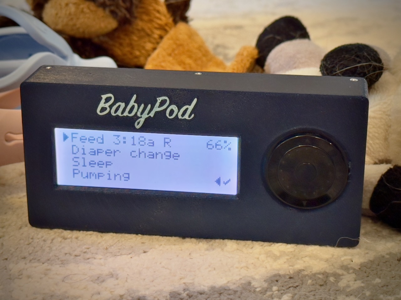 An assembled and running BabyPod
 -
Busy Buttons - noisy glowy buttons for babies and toddlers I had a collection of spare parts from Adafruit laying around. My toddler loves mashing buttons, particularly ones that make noise, so I decided to turn those spare parts into something they'd enjoy. As for my own sanity, it'll diminish as the sounds play relentlessly, but I built in a secret "mute" cheat code. I used Adafruit's arcade buttons which can withstand a lot of toddler smashing and used a massive battery so it'll almost never need charging.
You can view more about the project on Printables and see the source code and instructions on GitHub to make your own. The enclosure is 3D printed and the software runs on an ESP32-S2 Feather with CircuitPython.
As a much more advanced project, I also created BabyPod: an interface to Baby Buddy written in a lot of CircuitPython.

-
A Neopixel Floor Lamp with a Twist This is probably the coolest thing I have built with Adafruit electronics! When I viewed the learn guide describing the Floor Lamp with NeoPixels and WLED Custom Animations by Erin St Blaine I knew that I just had to build this work of art. I tend to like building things with wood, so my adaption of Erin's design for the most part replaces some elements with wood structures. I was pleasantly surprised with the results!
Materials
For the most part I followed Erin's design. My parts list is as follows:

-
CircuitPython Core Dev & Debug Tricks This is an evolving collection of tips and tricks about working on the CircuitPython core and related libraries. Topics include code analysis and debugging, working with git and GitHub, maintaining documentation, and install/config for dev tools. Mostly these are notes to future-me, but perhaps they will also help other people who want to improve CircuitPython.
Control Flow Graphs
When you're getting started working on a new-to-you module of complex code, it can be pretty hard to build a picture in your head of how the code works just from reading the text. Fortunately, there are tools which can analyze source code and build actual pictures for you with directed graphs of which functions call which other functions.
Below are some examples of how I've been generating graphs of control flow between the various functions in CircuitPython's usb module and TinyUSB library dependency. To make the graphs, I use Debian with the
cflowcode analysis tool to generate agraphviz(.dot) graph file, then turn that into a PNG image to view with themirageimage viewer. Formirageto work, you need to run the last command in a terminal in X (vnc or physical display will work, but not ssh).shared-bindings/usb/*

-
Fruit Jam Two Gamepad Demo This is my third iteration of a CircuitPython USB host gamepad tester, now with support for two controllers. The main loop in code.py uses asyncio to improve code readability. There's a new boot keyboard to gamepad mapper. For hot-swapping controllers, I devised an unplug detection heuristic to work around limitations in the current CircuitPython USB host implementation. Player numbers get assigned according to Fruit Jam top plate silkscreen port numbers. Player 1 gets USB 1, and Player 2 gets USB 2.
This demo project is meant to help folks who want to make Fruit Jam libraries for writing games. I don't plan to make a library on my own, but I wrote this code with library-making in mind in case somebody else wants to. Note that some of the performance and stability workarounds included here may become unnecessary once USB host implementation bugs get fixed.
The code here was written and tested with CircuitPython 10.0.0-beta.2 on a rev D Fruit Jam that I bought from the first production batch that went up in the shop.
Related work:
- Fruit Jam Gamepad Tester guide (my previous gamepad tester)
- Fruit Jam Fruitris (Tetris) game guide by @relic-se
- Feather TFT Gamepad Tester with Sprites guide (my original gamepad tester)
Overview

-
Fruit Jam Fruitris (Tetris) Parts
I am using a production revision D Fruit Jam board. Most additional components can likely be found around the house such as HDMI cable & display, headphones, power supply, etc. The controller system is designed to be as compatible as possible. So, most USB controller devices should work or even a USB keyboard.
It is possible to use a Metro RP2350 which is discussed in learn guides such as Larsio Paint Music., but this guide will not discuss that procedure nor has the software been tested within that environment.
From the Adafruit Shop
Controls
Action Keyboard Gamepad Buttons Move Left Left Arrow Left Move Right Right Arrow Right Rotate Clockwise Up Arrow or X Up or A Button #2 Drop: Soft Down Arrow Down Button #1 Drop: Hard Z B Quit (reload) Enter Start Button #3 


